HT9015 View Datasheet(PDF) - Holtek Semiconductor
Part Name
Description
Manufacturer
HT9015 Datasheet PDF : 23 Pages
| |||
Preliminary
HT9015
Functional Description
The HT9015 is a signal chip RF IC for cordless
phone applications. It has applications for
46/49MHz cordless phones as well as CT0 cord-
less phones that have frequency bands between
20MHz and 60MHz. This chip enables external
components in the base set and hand set radio
section application circuits to be reduced.
The HT9015 is manufactured or a special pro-
cess called BiCMOS, or bipolar process and
CMOS process. Because the RF and IF parts
need high frequency actions such as mixer,
VCO, IF amplifier and demodulator, those
parts are implemented in high performance bi-
polar circuits. The other digital functions are
designed using CMOS circuits. Sometimes this
chip is known as ²COMBO², the meaning of
COMBO is one chip combined with RF, IF and
PLL parts.
The HT9015 provides data latch interface con-
trolled by a microcontroller. There are four in-
ternal registers inside the HT9015; TX
(transmitter) divider, RX (receiver) Divider,
REF (reference) divider and Control Register.
All registers can be set through the data latch
control interface. The data latch control inter-
face contains DATA, CLK and STB control sig-
nals.
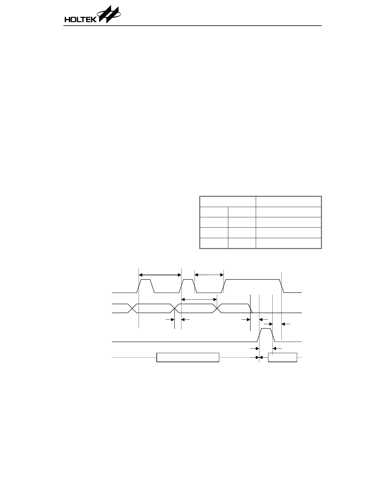
Input timing for serial data
Data is read on the timing of the rising edge of
CLK. When STB receives a high signal, DATA
³1ms
³ 0 .2 m s
in the shift register is sent into the latch to con-
trol the block, see the input timing for serial
data as shown below.
Serial data format of four registers
According to previous input timing Specs, the
HT9015 can be easily set up using four regis-
ters. The TX divider determines the TX PLL
locked frequency; the RX divider determines
the RX PLL locked frequency; the REF divider
determines the TX and RX PLL frequency ref-
erence which is also called channel space. The
control register is an important unit which con-
trols the radio link, voice control and power sav-
ing during base set and hand set
communication.
All data format contains 20 bits, but some regis-
ters need only 16 bits, They have a common
field of 20 bits data format called ²code² which
determine what data belongs to whom. See the
table below.
Code
Register
1
1
REF register
1
0
TX register
0
1
RX register
0
0
Control register
Four register selection
³ 0 .2 m s
C LK
D ATA
³ 0 .2 m s
³ 0 .1 m s
³ 0 .1 m s
³ 0 .2 m s
STB
O p e r a tio n S ta te
P r e v io u s S ta te
Figure 1 Input timing for serial data
³ 0 .2 m s
N e w S ta te
10
April 10, 2000
Share Link: 