VN920SO(2013) View Datasheet(PDF) - STMicroelectronics
Part Name
Description
Manufacturer
VN920SO Datasheet PDF : 35 Pages
| |||
Electrical specifications
VN920
2.3
Note:
Electrical characteristics
Values specified in this section are for 8V < VCC < 36V; -40°C < Tj < 150°C, unless otherwise
stated.
Table 5. Power
Symbol
Parameter
Test conditions
VCC Operating supply voltage
VUSD Under-voltage shutdown
VOV Over-voltage shutdown
RON On-state resistance
IOUT = 10A; Tj = 25°C;
IOUT = 10A;
IOUT = 3A; VCC = 6V
VCLAMP Clamp voltage
ICC = 20mA
Off-state; VCC = 13V;
VIN = VOUT = 0V
Min. Typ. Max. Unit
5.5 13 36 V
3
4 5.5 V
36
V
16 mΩ
32 mΩ
55 mΩ
41 48 55 V
10 25 µA
IS Supply current
Off-state; VCC = 13V;
VIN = VOUT = 0V; Tj = 25°C
10 20 µA
On-state; VCC = 13V; VIN = 5V;
IOUT = 0A; RSENSE = 3.9 kΩ
IL(off1) Off-state output current VIN = VOUT = 0V
0
IL(off2) Off-state output current VIN = 0V; VOUT = 3.5V
-75
IL(off3)
Off-state output current
VIN = VOUT = 0V; VCC = 13V;
Tj = 125°C
IL(off4)
Off-state output current
VIN = VOUT = 0V; VCC = 13V;
Tj = 25°C
VCLAMP and VOV are correlated. Typical difference is 5V.
5 mA
50 µA
0 µA
5 µA
3 µA
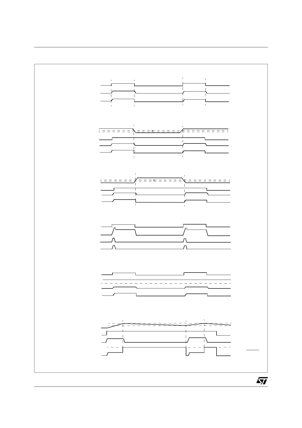
Table 6. Switching (VCC=13V)
Symbol
Parameter
Test conditions
td(on) Turn-on delay time RL = 1.3Ω (see Figure 4.)
td(off) Turn-off delay time RL = 1.3Ω (see Figure 4.)
dVOUT/dt(on) Turn-on voltage slope RL = 1.3Ω (see Figure 4.)
dVOUT/dt(off) Turn-off voltage slope RL = 1.3Ω (see Figure 4.)
Min. Typ. Max. Unit
50
50
See Figure 10.
See Figure 12.
µs
µs
V/µs
V/µs
8/34
Share Link: 