M34280E1FP View Datasheet(PDF) - MITSUBISHI ELECTRIC
Part Name
Description
Manufacturer
M34280E1FP
MITSUBISHI ELECTRIC

M34280E1FP Datasheet PDF : 47 Pages
| |||
MITSUBISHI MICROCOMPUTERS
4280 Group
SINGLE-CHIP 4-BIT CMOS MICROCOMPUTER for INFRARED REMOTE CONTROL TRANSMITTERS
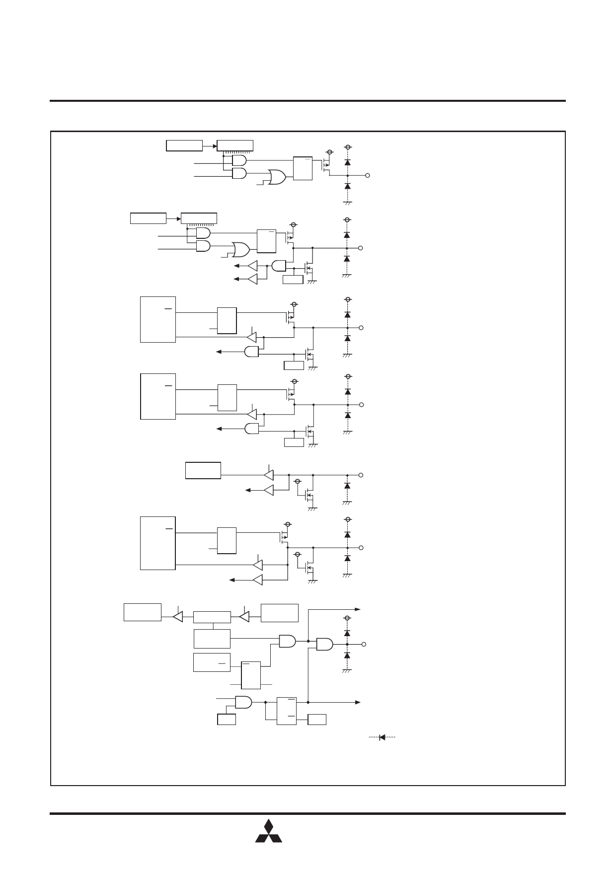
PORT BLOCK DIAGRAMS
Register Y
Decoder
SD instruction
RD instruction
CLD instruction
SQ
R
(Note 1)
Ports D0–D6
Register Y
Decoder
SD instruction
RD instruction
CLD instruction
Skip decision (SZD instruction)
Key-on wakeup input
SQ
R
PU02
(Note 1)
Pull-down
transistor
Port D7 (Note 4)
Register A
A0
OEA
instruction
A0
DQ
IAE instruction
T
Key-on wakeup input
Register A
A1
OEA
instruction
A1
PU00
DQ
IAE instruction
T
Key-on wakeup input
PU01
(Note 1)
Port E0 (Note 4)
Pull-down
transistor
(Note 1)
Port E1 (Note 4)
Pull-down
transistor
Register A
A2
IAE instruction
Key-on wakeup input
Pull-down
transistor
Port E2 (Note 4)
(Note 1)
Register A
Ai
(Note 2)
OGA
instruction
Ai
DQ
T IAG instruction
Key-on wakeup input
(Note 1)
Ports G0–G3 (Note 4)
Pull-down
transistor
Register A TAC instruction
TCA instruction
Register A
Aj (Note 3)
Register C
Aj (Note 3)
Carrier wave
output circuit
To timer 1
CARRY
(Note 1)
Port CARR
Register A
A3
OCRA instruction
Timer 1 underflow signal
DQ
TR
V12
TCA
instruction
DQ
TR
V10
Carrier wave
output control
signal
Notes 1:
This symbol represents a parasitic diode.
2: i represents bits 0 to 3.
3: j represents bits 0 to 2.
4: Applied voltage must be less than VDD.
MITSUBISHI
ELECTRIC
5
Share Link: