M34280E1FP View Datasheet(PDF) - MITSUBISHI ELECTRIC
Part Name
Description
Manufacturer
M34280E1FP
MITSUBISHI ELECTRIC

M34280E1FP Datasheet PDF : 47 Pages
| |||
MITSUBISHI MICROCOMPUTERS
4280 Group
SINGLE-CHIP 4-BIT CMOS MICROCOMPUTER for INFRARED REMOTE CONTROL TRANSMITTERS
FUNCTION BLOCK OPERATIONS
CPU
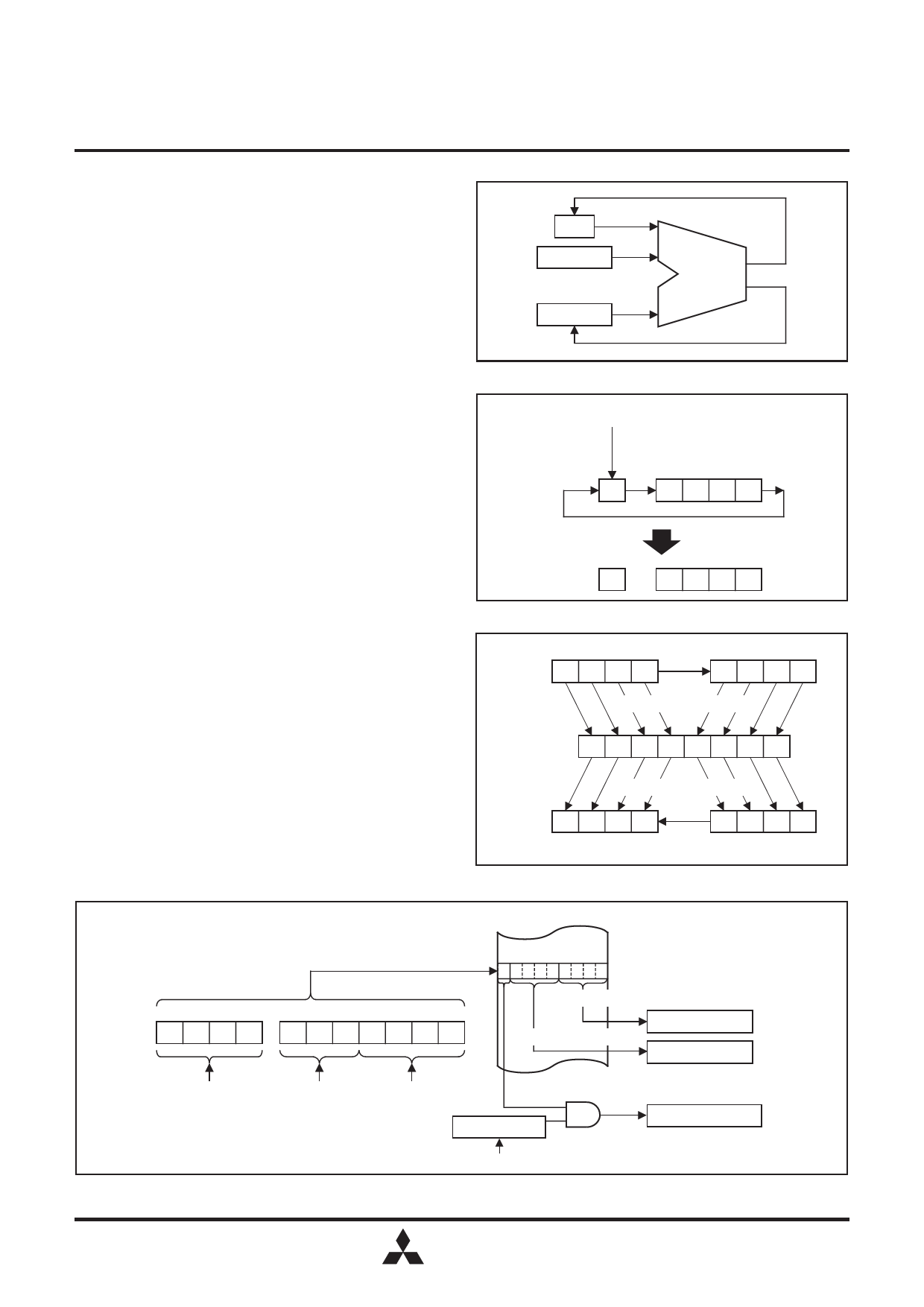
(1) Arithmetic logic unit (ALU)
The arithmetic logic unit ALU performs 4-bit arithmetic such
as 4-bit data addition, comparison, and bit manipulation.
(2) Register A and carry flag
Register A is a 4-bit register used for arithmetic, transfer,
exchange, and I/O operation.
Carry flag CY is a 1-bit flag that is set to “1” when there is a
carry with the AMC instruction (Figure 1).
It is unchanged with both A n instruction and AM instruction.
The value of A0 is stored in carry flag CY with the RAR
instruction (Figure 2).
Carry flag CY can be set to “1” with the SC instruction and
cleared to “0” with the RC instruction.
(3) Registers B and E
Register B is a 4-bit register used for temporary storage of 4-
bit data, and for 8-bit data transfer together with register A.
Register E is an 8-bit register. It can be used for 8-bit data
transfer with register B used as the high-order 4 bits and
register A as the low-order 4 bits (Figure 3).
(4) Register D
Register D is a 3-bit register.
It is used to store a 7-bit ROM address together with register
A and is used as a pointer within the specified page when the
TABP p, BLA p, or BMLA p instruction is executed (Figure 4).
(CY)
(M(DP))
Addition
<Carry>
ALU
(A)
<Result>
Fig. 1 AMC instruction execution example
<Set>
<Clear>
SC instruction RC instruction
CY
A3 A2 A1 A0
<Rotation>
RAR instruction
A0
CY A3 A2 A1
Fig. 2 RAR instruction execution example
Register B TAB instruction Register A
B3 B2 B1 B0
A3 A2 A1 A0
TEAB instruction
Register E ER7ER6ER5ER4ER3ER2ER1ER0
TABE instruction
B3 B2 B1 B0
A3 A2 A1 A0
Register B TBA instruction Register A
Fig. 3 Registers A, B and register E
TABP p instruction
Specifying address
ROM
8
4
0
PCH
p3 p2 p1 p0
PCL
DR2 DR1 DR0 A3 A2 A1 A0
Low-order 4 bits
Middle-order 4 bits
Register A (4)
Register B (4)
Immediate field
value p
The contents The contents Most significant 1 bit
of register D of register A
URS flag (1)
Carry flag CY (1)
Fig. 4 TABP p instruction execution example
URSC instruction
MITSUBISHI
6
ELECTRIC
Share Link: