LTC1545CG View Datasheet(PDF) - Linear Technology
Part Name
Description
Manufacturer
LTC1545CG Datasheet PDF : 16 Pages
| |||
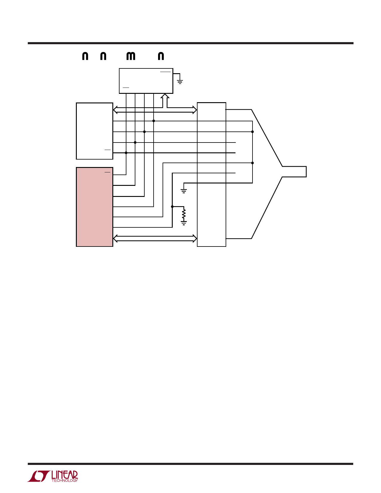
APPLICATIONS INFORMATION
21
LATCH
LTC1344A
DCE/
DTE M2 M1 M0 (DATA)
22 23 24 1
(DATA)
11
M0
12
LTC1543 M1
13
M2
14
DCE/DTE
CONNECTOR
NC
NC
LTC1545
14
DCE/DTE
13
M2
12
M1
11
LTC1545 M0
15
D4ENB
16
R4EN
(DATA)
VCC
CABLE
10k
1545 F10
Figure 10: Single Port DCE V.35 Mode Selection in the Cable
with the termination in the cable head or separate termina-
tions are built on the board and a custom cable routes the
signals to the appropriate termination. Switching the
terminations with FETs is difficult because the FETs must
remain off even though the signal voltage is beyond the
supply voltage for the FET drivers or the power is off.
Using the LTC1344A along with the LTC1543/LTC1545
solves the cable termination switching problem. Via soft-
ware control, the LTC1344A provides termination for the
V.10 (RS423), V.11 (RS422), V.28 (RS232) and V.35
electrical protocols.
V.10 (RS423) Interface
A typical V.10 unbalanced interface is shown in Figure 11.
A V.10 single-ended generator output A with ground C is
connected to a differential receiver with inputs A' con-
nected to A, and input C' connected to the signal return
ground C. Usually, no cable termination is required for
V.10 interfaces, but the receiver inputs must be compliant
with the impedance curve shown in Figure 12.
The V.10 receiver configuration in the LTC1545 is shown
in Figure 13. In V.10 mode switch S3 inside the LTC1545
is turned off. The noninverting input is disconnected
inside the LTC1545 receiver and connected to ground.The
cable termination is then the 30k input impedance to
ground of the LTC1545 V.10 receiver.
V.11 (RS422) Interface
A typical V.11 balanced interface is shown in Figure 14. A
V.11 differential generator with outputs A and B with
ground C is connected to a differential receiver with
ground C', inputs A' connected to A, B' connected to B. The
V.11 interface has a differential termination at the receiver
end that has a minimum value of 100Ω. The termination
resistor is optional in the V.11 specification, but for the
high speed clock and data lines, the termination is required
to prevent reflections from corrupting the data. The
receiver inputs must also be compliant with the imped-
ance curve shown in Figure 12.
9
Share Link: 