LTC1546I View Datasheet(PDF) - Linear Technology
Part Name
Description
Manufacturer
LTC1546I Datasheet PDF : 20 Pages
| |||
APPLICATIO S I FOR ATIO
(DATA)
11
M0
12
LTC1546 M1
13
M2
14
DCE/DTE
14
DCE/DTE
13
M2
LTC1544
12
M1
11
M0
(DATA)
CONNECTOR
NC
NC
LTC1546
CABLE
1546 F18
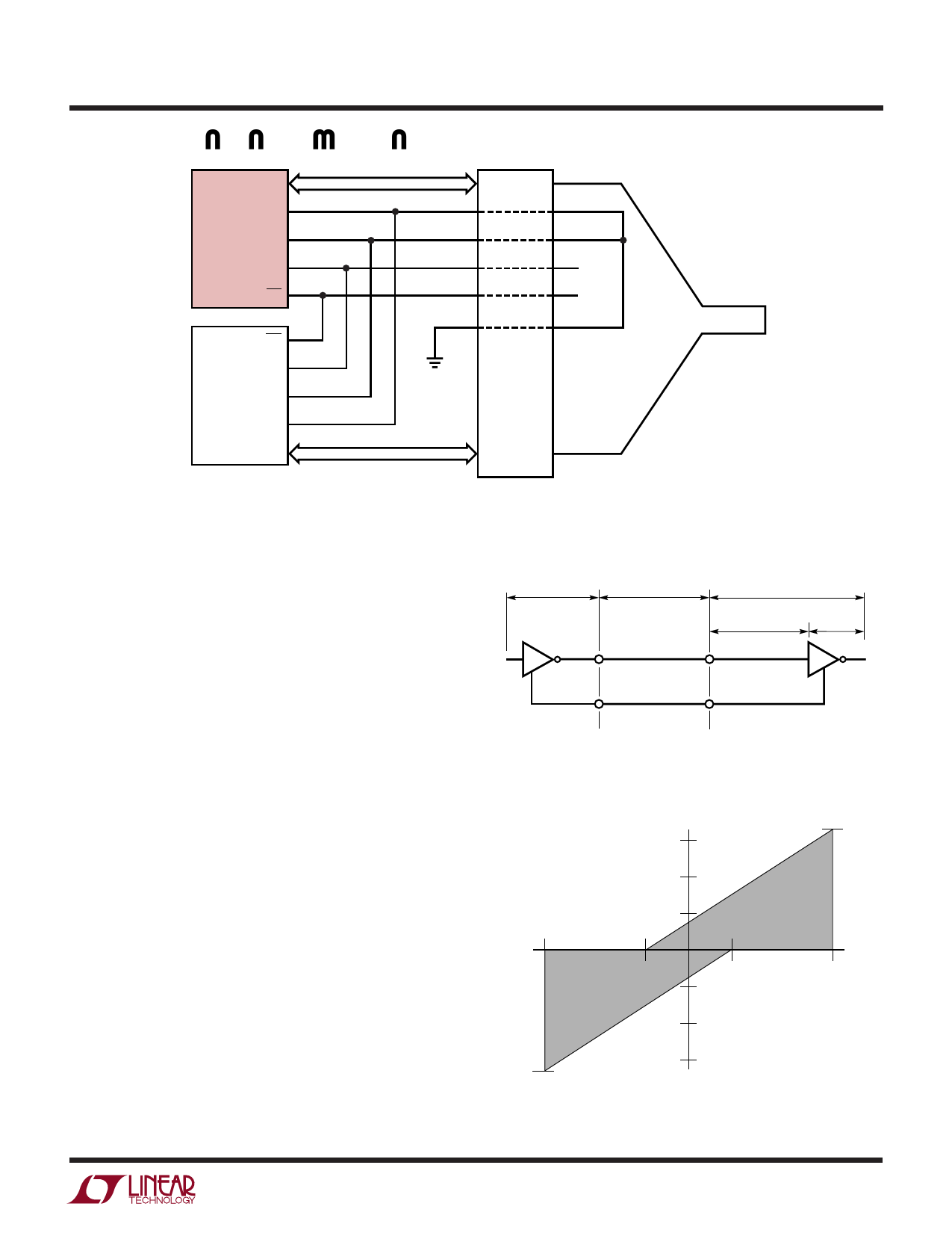
Figure 18: Single Port DCE V.35 Mode Selection in the Cable
V.10 (RS423) Interface
All V.10 drivers and receivers necessary for the RS449,
EIA530, EIA530-A, V.36 and X.21 protocols are imple-
mented on the LTC1544.
A typical V.10 unbalanced interface is shown in Figure 19.
A V.10 single-ended generator with output A and ground
C is connected to a differential receiver with input A' con-
nected to A, and ground C' connected via the signal return
to ground C. Usually, no cable termination is required for
V.10 interfaces, but the receiver inputs must be compliant
with the impedance curve shown in Figure 20.
The V.10 receiver configuration in the LTC1544 is shown
in Figure 21. In V.10 mode, switch S3 inside the LTC1544
is turned off. The noninverting input is disconnected
inside the LTC1544 receiver and connected to ground. The
cable termination is then the 30k input impedance to
ground of the LTC1544 V.10 receiver.
V.11 (RS422) Interface
A typical V.11 balanced interface is shown in Figure 22. A
V.11 differential generator with outputs A and B and
ground C is connected to a differential receiver with input
A' connected to A, input B' connected to B, and ground C'
connected via the signal return to ground C. The V.11
GENERATOR
BALANCED
INTERCONNECTING
CABLE
LOAD
CABLE
TERMINATION
RECEIVER
A
A'
C
C'
1546 F19
Figure 19. Typical V.10 Interface
IZ
3.25mA
–10V
–3V
3V
VZ
10V
–3.25mA
1546 F20
Figure 20. V.10 Receiver Input Impedance
11
Share Link: 