BA7207AK View Datasheet(PDF) - ROHM Semiconductor
Part Name
Description
Manufacturer
BA7207AK Datasheet PDF : 17 Pages
| |||
Video ICs
BA7207AS / BA7207AK
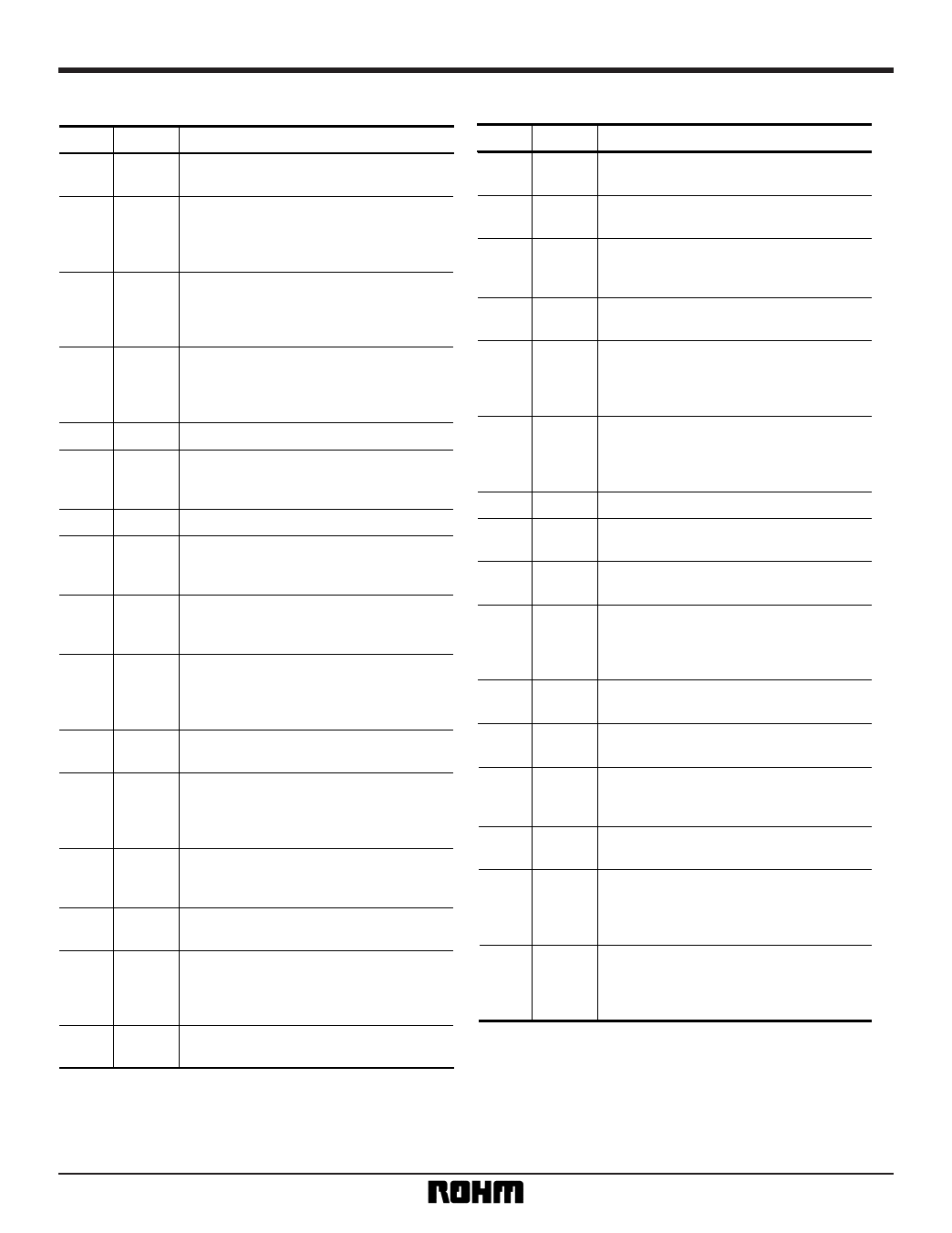
•Pin descriptions
Pin No. Pin name
Function
Recording system input.
1 (40) RECIN Input the REC system chroma signal.
2 (42)
MUL
PB sync gate output.
Test pin. Outputs the chroma signal after it is
multiplied by four and passed through the sync
gate. Normally connected to VCC to prevent
interference.
3 (43)
FADJ1
Filter fo adjustment pin 1.
Used to adjust fo for the equalizer, 1.1MHz BPF
and 2.2MHz BPF. Connect a resistor and variable
resistor from this pin to GND.
4 (44)
FADJ2
Filter fo adjustment pin 2.
Used to adjust fo for the bell filter, 4.3MHz BPF-A
and 4.3MHz BPF-B. Connect a resistor and
variable resistor from this pin to GND.
5 (1) GND1 Ground.
PB system preamplifier output.
6 (2) AMPOUT Connect to GND via a variable resistor to adjust
the level, and input to pin 8.
7 (3) GND Ground.
PB system output amplifier input.
8 (5) SCMPIN Input the level-adjusted PB system SECAM
chroma signal.
9 (7)
DET
Phase comparator output.
Connect to GND via a RC LPF to obtain the error
voltage.
10 (9)
VCO
VCO oscillator frequency control pin.
The error voltage is input via a resistor.
Connected to GND via free-running frequency
setting resistor.
PB system output.
11 (10) PBOUT Outputs the PB system chroma signal.
12 (11)
SGADJ
Fine adjustment for the sync gate phase.
The voltage from a resistor divider is used for fine
adjustment of the gate phase of the sync gate.
Normally open.
13 (12)
SGC
Sync gate timing output.
Test pin. Outputs the REC sync gate timing.
Normally open.
PAL PB system input.
14 (13) PALPIN Input chroma signal for the PAL PB system.
15 (14)
DIV
Divide-by-four divider output.
Test pin. Outputs the chroma signal after it has
been divided by four. Normally connected to VCC
to prevent interference.
Delayed sync signal input.
16 SYNCIN Input the synchronously-separated composite
Pin No. Pin name
Function
17 (18)
BWL
Chroma killer mode setting . "L" sets the IC in
chroma killer mode.
18 (20)
PBIN
PB system input .
Input chroma signal for the PB system.
REC / PB mode switch.
19 (21) RECH Set to open or "H" for REC mode, "L" for PB
mode.
20 (22)
CREF3
Bias terminal for the limiter amplifier before × 2.
Connect to GND via a capacitor.
21 (23) CTL
22 (24) LAO
SECAM / PAL output switch.
Selects the signal output for the REC / PB
terminal. Set to open or "H" for SECAM output
mode, "L" for PAL mode.
Limiter amplifier output.
Test pin. Outputs the amplitude-limited chroma
signal. Normally connected to VCC to prevent
interference.
23 (25)
24 (27)
VCC
LAIN
Power supply.
Limiter amplifier input.
Input the de-emphasised chroma signal.
Limiter amplifier bias pin 1.
25 (29) CREF1 Connect to GND via a capacitor.
26 (31)
ABELO
REC BELL output. When in REC mode,
de-emphasised chroma signal is output via REC
BELL. When in PB mode, the PB system chroma
signal is output after being multiplied by four.
27 (32)
CREF2
Limiter amplifier bias pin 2.
Connect to GND via a capacitor.
28
(33)
RECOUT
REC
REC
system
system
output.
chroma
signal
output.
29 (34)
TRAP
TRAP connection.
Connect TRAP that rejects spurious signal
component after × 2 multiplication.
30 (35)
PALRIN
PAL REC system input.
PAL REC system chroma signal input.
31 (36) VREG
Regulated voltage output.
Output for the regulated 2.5V reference voltage
used for internal biasing. Connect to GND via a
bypass capacitor.
32 (38) × 40
× 4 multiply output.
Test pin. Outputs the chroma signal after it is
multiplied by four. Normally connected to VCC to
prevent interference.
BA7207AK pin numbers are given in brackets.
3
Share Link: 