AN-9008 View Datasheet(PDF) - Fairchild Semiconductor
Part Name
Description
Manufacturer
AN-9008 Datasheet PDF : 9 Pages
| |||
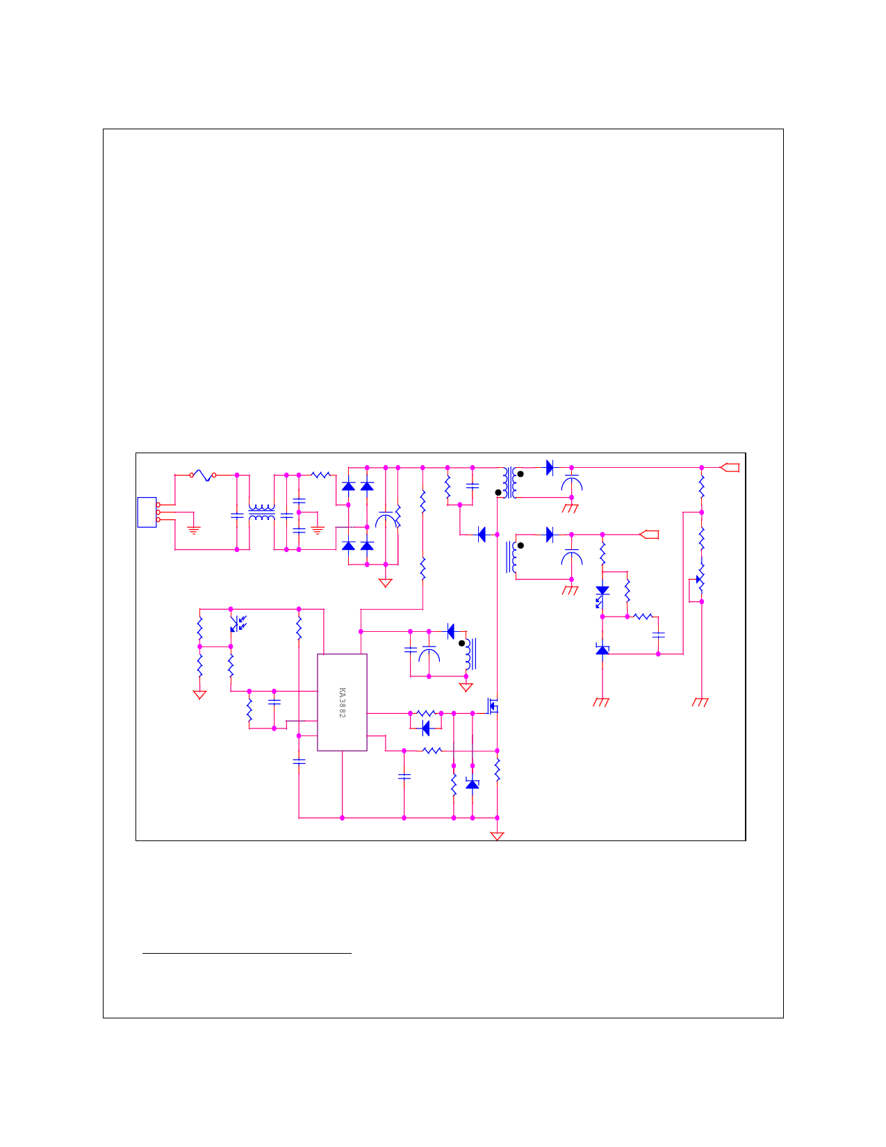
Performance in a Flyback Converter
Figure 3 shows the design of a commercially available 60 watt flyback converter with two outputs
(+160V, +15V), operating at a switching frequency of 80kHz and an input voltage of 220VAC. This
type of switching power supply is used for applications, such as monitors, TVs, and miscellaneous
instruments, requiring multiple output voltages . This discontinuous mode flyback converter, using
a KA3882 current mode controller, features good voltage tracking with the use of pulse by pulse
current sensing on the primary side, and an isolated secondary feedback loop. The PWM IC
KA3882 directly drives the power MOSFET.
As the power MOSFET sequentially turns on and off, energy is stored in the transformer core dur-
ing the on time, and is then transferred to the output capacitor during the off time. When the power
MOSFET turns off, the energy stored in the leakage inductance causes a voltage spike across the
drain-to-source terminal of the power MOSFET, which amounts to at least twice the input voltage
(Vin + nVo + leakage inductance voltage1). Most applications need clamp circuits to restrict this
voltage spike from exceeding the BVdss rating of a MOSFET. A power MOSFET must have high
voltage capability with lower on-resistance and smaller gate charge for higher efficiency.
2
1
Fuse
L1
3
2
C2
C1
1
Vin=220VAC
U2
R6
R7
R8
1
2
R1
C3
C4
D1
C5
R2
R10
U1
C9
8
7
R5
R3
T1
1
5
D6
1
2
C12
C6
4
8
D2
2
1
D7
1
2
Vout2
5V 0.8A
R14
C13
R4
R16
Vout1
R18
160V 0.3A
R19
2
R20
D3
2
1
C10
R17
1
2
C14
U3
R9
C7
2
1
6
453
C8
R11
1
2
2
1
D4
1
2
R11
C11
R13
QFET(FQP7N60)
Q1
1 or Conventional
MOSFET
D5 R14
Figure 3: Flyback Converter Circuit Diagram
1. 'n' indicates a turns ratio of the transformer windings. The voltage of Vin + nVo + leakage inductance voltage of the transformer appears at
the primary side.
Rev D, July 2000
3
Share Link: 