AT88SC25616C View Datasheet(PDF) - Atmel Corporation
Part Name
Description
Manufacturer
AT88SC25616C Datasheet PDF : 14 Pages
| |||
AT88SC25616C
Protocol Selection
Asynchronous
T = 0 Protocol
Synchronous
2-wire Serial Interface
5017DSŌĆōSMEMŌĆō7/04
The AT88SC25616C supports two different communication protocols.
ŌĆó Smart Card Applications: The asynchronous T = 0 protocol defined by ISO 7816-3
is used for compatibility with the industryŌĆÖs standard smart card readers.
ŌĆó Embedded Applications: A 2-wire serial interface is used for fast and efficient
communication with logic or controllers.
The power-up sequence determines which of the two communication protocols will be used.
This power-up sequence complies with ISO 7816-3 for a cold reset in smart card
applications.
ŌĆó VCC goes high; RST, I/O-SDA and CLK-SCL are low.
ŌĆó Set I/O-SDA in receive mode.
ŌĆó Provide a clock signal to CLK-SCL.
ŌĆó RST goes high after 400 clock cycles.
The device will respond with a 64-bit ATR code, including historical bytes to indicate the mem-
ory density within the CryptoMemory family. Once the asynchronous mode has been
selected, it is not possible to switch to the synchronous mode without powering off the device.
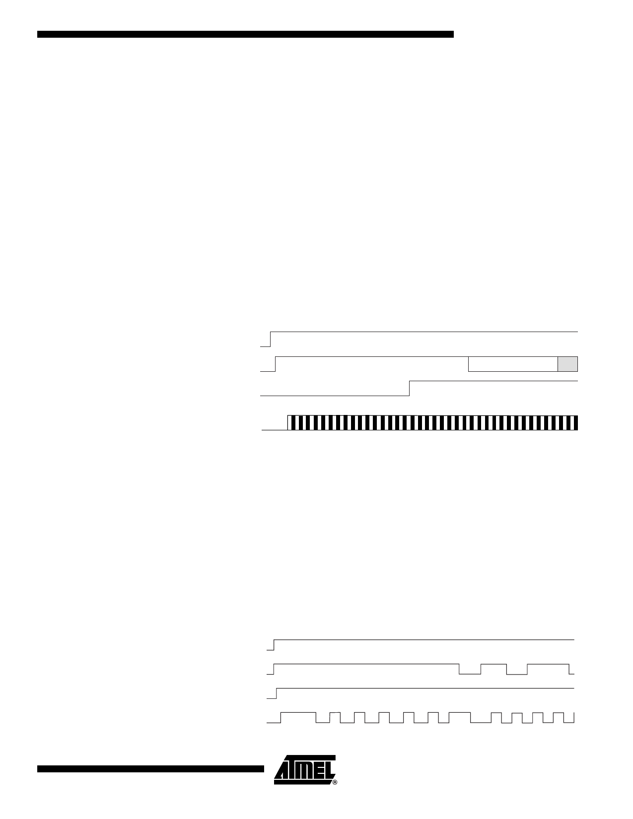
Figure 2. Asynchronous T = 0 Protocol (Gemplus Patent)
Vcc
I/O-SDA
ATR
RST
CLK-SCL
After a successful ATR, the Protocol and Parameter Selection (PPS) protocol, as defined
by ISO 7816-3, may be used to negotiate the communications speed with CryptoMemory
devices 32 Kbits and larger. CryptoMemory supports D values of 1, 2, 4, 8, 12, and 16 for
an F value of 372. Also supported are D values of 8 and 16 for F = 512. This allows selec-
tion of 8 communications speeds ranging from 9600 baud to 153,600 baud.
The synchronous mode is the default after powering up VCC due to the internal pull-up
on RST. For embedded applications using CryptoMemory in standard plastic packages,
this is the only communication protocol.
ŌĆó Power-up VCC, RST goes high also.
ŌĆó After stable VCC, CLK-SCL and I/O-SDA may be driven.
ŌĆó Power-up VCC, RST goes high also.
ŌĆó After stable VCC, CLK-SCL and I/O-SDA may be driven.
Figure 3. Synchronous 2-wire Protocol
Vcc
I/O-SDA
RST
CLK-SCL
1 2345
Note: Five clock pulses must be sent before the first command is issued.
5
Share Link: 