IS42RM16800E View Datasheet(PDF) - Integrated Silicon Solution
Part Name
Description
Manufacturer
IS42RM16800E Datasheet PDF : 25 Pages
| |||
IS42SM81600E / IS42SM16800E / IS42SM32400E
IS42RM81600E / IS42RM16800E / IS42RM32400E
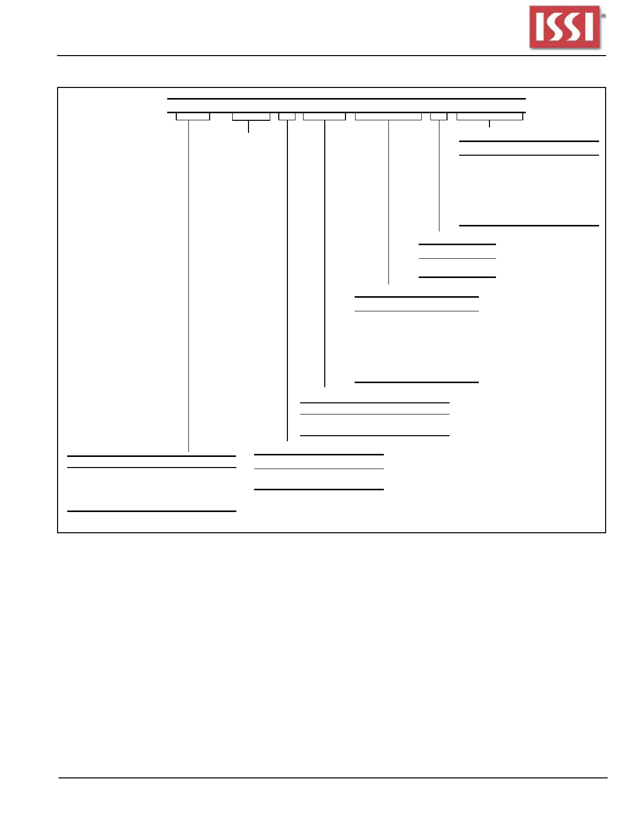
MODE REGISTER DEFINITION
BA1
0
0
1
1
BA0
0
1
0
1
BA1 BA0 A11 A10 A9 A8 A7 A6 A5 A4 A3 A2 A1 A0 Address Bus (Ax)
Mode Register (Mx)
Reserved(1)
Burst Length
M2 M1 M0
000
001
010
011
100
101
110
111
M3=0
1
2
4
8
Reserved
Reserved
Reserved
Full Page
M3=1
1
2
4
8
Reserved
Reserved
Reserved
Reserved
Burst Type
M3
Type
0
Sequential
1 Interleaved
Latency Mode
M6 M5 M4
000
001
010
011
100
101
110
111
CAS Latency
Reserved
Reserved
2
3
Reserved
Reserved
Reserved
Reserved
Operating Mode
M8 M7
00
——
M6-M0
Defined
—
Mode
Standard Operation
All Other States Reserved
Mode Register Definition
Program Mode Register
Reserved
Program Extended Mode Register
Reserved
Write Burst Mode
M9
Mode
0
Programmed Burst Length
1
Single Location Access
To ensure compatibility with future devices,
should program A11, A10 = "0"
Burst Length
Read and write accesses to the SDRAM are burst oriented, with the burst length being programmable, as shown in
MODE REGISTER DEFINITION. The burst length determines the maximum number of column locations that can
be accessed for a given READ or WRITE command. Burst lengths of 1, 2, 4 or 8 locations are available for both the
sequential and the interleaved burst types, and a full-page burst is available for the sequential type. The full-page burst
is used in conjunction with the BURST TERMINATE command to generate arbitrary burst lengths. Reserved states
should not be used, as unknown operation or incompatibility with future versions may result.
When a READ or WRITE command is issued, a block of columns equal to the burst length is effectively selected. All
accesses for that burst take place within this block, meaning that the burst will wrap within the block if a boundary is
reached. The block is uniquely selected by A1-A7 (x32), A1-A8 (x16) or A1-A9 (x8) when the burst length is set to two;
by A2-A7 (x32), A2-A8 (x16) or A2-A9 (x8) when the burst length is set to four; and by A3-A7 (x32), A3-A8 (x16) or
A3-A9 (x8) when the burst length is set to eight. The remaining (least significant) address bit(s) are used to select the
starting location within the block. Full-page bursts wrap within the page if the boundary is reached.
Integrated Silicon Solution, Inc. - www.issi.com
9
Rev. B
04/15/2011
Share Link: 