MAX7705C View Datasheet(PDF) - Maxim Integrated
Part Name
Description
Manufacturer
MAX7705C Datasheet PDF : 8 Pages
| |||
µP Power-Supply Monitor
with Reset
150
TA = +25°C
100
50
10ns
0
10
100
1k
10k
RESET COMPARATOR OVERDRIVE, VTH - VCC (mV)
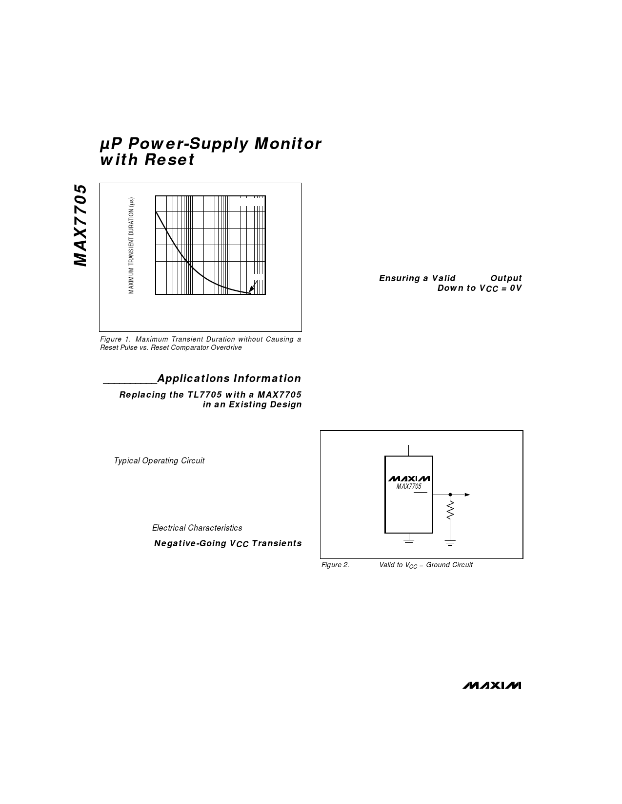
Figure 1. Maximum Transient Duration without Causing a
Reset Pulse vs. Reset Comparator Overdrive
__________Applications Information
Replacing the TL7705 with a MAX7705
in an Existing Design
The MAX7705 has only three active pins: VCC, GND,
and RESET. When using a TL7705 with a µP that has
a RESET input, simply plug the MAX7705 into the
same socket and omit the RESET pull-up resistor, reset
timing capacitor, and reference bypass capacitor (see
the Typical Operating Circuit).
The MAX7705 monitors the VCC voltage and asserts
reset whenever VCC falls below the reset threshold.
The reset power-up delay is created by an internal
fixed oscillator. This delay is 100% tested and guaran-
teed over the full temperature range. The RESET out-
put both sources and sinks current (see RESET Output
Voltage in the Electrical Characteristics).
Negative-Going VCC Transients
The MAX7705 asserts RESET during power-up,
power-down, and brownout conditions. However, it is
relatively immune to short-duration negative-going VCC
transients (glitches).
Figure 1 shows typical transient duration vs. reset com-
parator overdrive for which the MAX7705 does not gen-
erate a reset pulse. The graph was generated using a
fast-edge, negative-going pulse applied to VCC, starting
1.5V above the actual reset threshold and ending below
the reset threshold by the magnitude indicated (reset
comparator overdrive). It indicates the typical maxi-
mum pulse width a negative-going VCC transient may
have without causing a reset pulse to be issued. As
the magnitude of the transient increases (goes farther
below the reset threshold), the maximum allowable
pulse width decreases. Typically, a VCC transient that
goes 100mV below the reset threshold and lasts 40µs
or less will not cause a reset pulse to be issued.
A 0.1µF bypass capacitor mounted as close as possible
to pin 2 (VCC) provides additional transient immunity.
Ensuring a Valid RESET Output
Down to VCC = 0V
When VCC falls below 1V, the MAX7705 RESET output
no longer sinks current; it becomes high impedance.
Therefore, high-impedance CMOS logic inputs con-
nected to the RESET output can drift to indeterminate
voltages. In most applications this presents no prob-
lem, as µP and other circuitry is generally inoperative
with VCC below 1V. In applications where the RESET
output must be valid down to 0V, adding a pull-down
resistor to the RESET pin (as shown in Figure 2) will
cause any stray leakage currents to flow to ground,
holding RESET low. The resistance value of R1 is not
critical. It should be about 100kΩ, which is large
enough not to load RESET and small enough to pull
RESET to ground.
VCC
MAX7705
RESET
R1
GND
Figure 2. RESET Valid to VCC = Ground Circuit
4 _______________________________________________________________________________________
Share Link: 