MAX8640YEXT25(2007-07) View Datasheet(PDF) - Maxim Integrated
Part Name
Description
Manufacturer
MAX8640YEXT25
(Rev.:2007-07)
(Rev.:2007-07)
Maxim Integrated

MAX8640YEXT25 Datasheet PDF : 11 Pages
| |||
Tiny 500mA, 4MHz/2MHz Synchronous
Step-Down DC-DC Converters
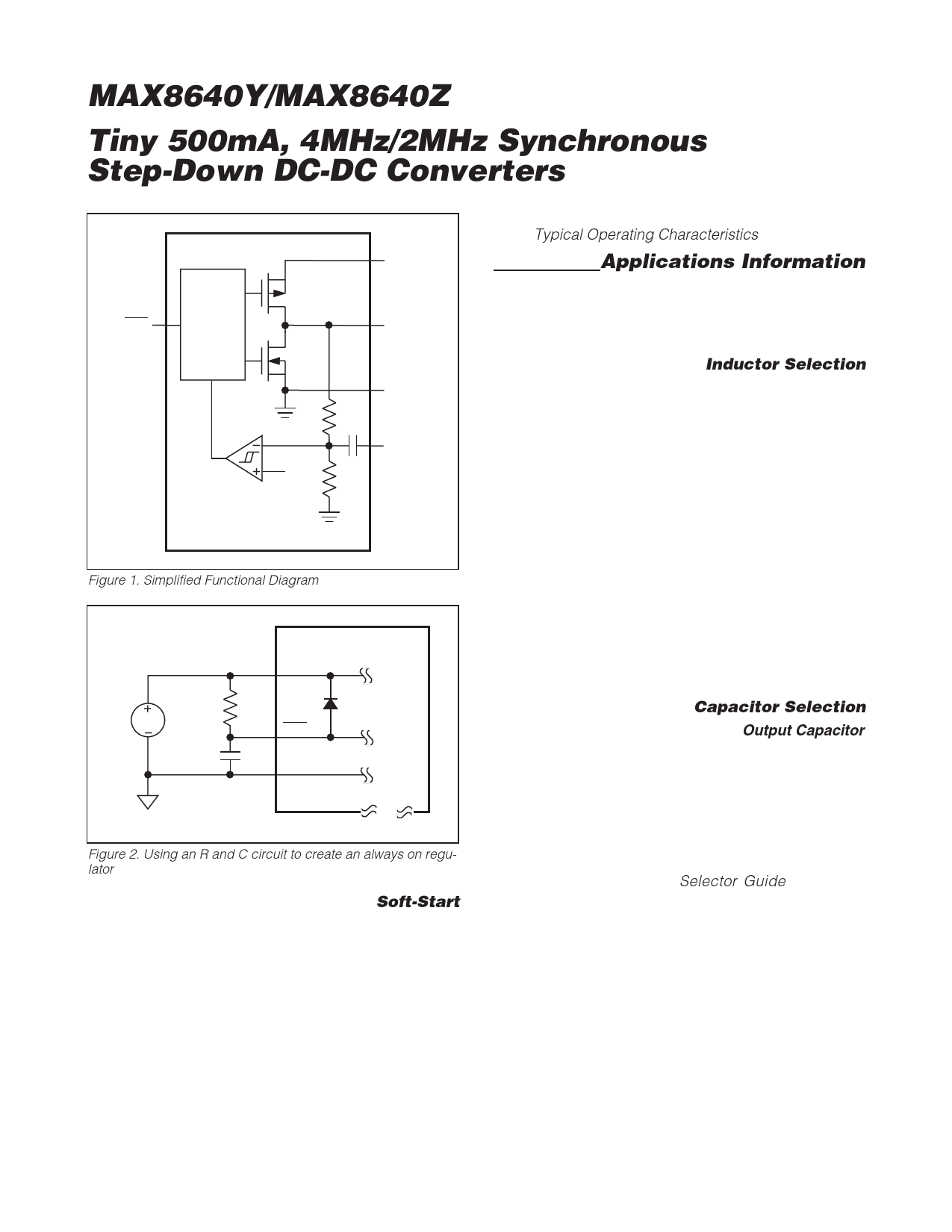
Soft-Start
The MAX8640Y/MAX8640Z include internal soft-start
circuitry that eliminates inrush current at startup, reduc-
ing transients on the input source. Soft-start is particu-
larly useful for higher impedance input sources, such
as Li+ and alkaline cells. See the Soft-Start Response
in the Typical Operating Characteristics.
Applications Information
The MAX8640Y/MAX8640Z are optimized for use with a
tiny inductor and small ceramic capacitors. The correct
selection of external components ensures high efficien-
cy, low output ripple, and fast transient response.
Inductor Selection
A 1µH inductor is recommended for use with the
MAX8640Z, and 2.2µH is recommended for the
MAX8640Y. A 1µH inductor is physically smaller but
requires faster switching, resulting in some efficiency
loss. Table 1 lists several recommended inductors.
It is acceptable to use a 1.5µH inductor with either the
MAX8640Y or MAX8640Z, but efficiency and ripple
should be verified. Similarly, it is acceptable to use a
3.3µH inductor with the MAX8640Y, but performance
should be verified.
For optimum voltage positioning of load transients,
choose an inductor with DC series resistance in the
75mΩ to 150mΩ range. For higher efficiency at heavy
loads (above 200mA) or minimal load regulation (but
some transient overshoot), the resistance should be
kept as low as possible. For light-load applications up
to 200mA, higher resistance is acceptable with very lit-
tle impact on performance.
Capacitor Selection
Output Capacitor
The output capacitor, C2, is required to keep the output
voltage ripple small and to ensure regulation loop sta-
bility. C2 must have low impedance at the switching fre-
quency. Ceramic capacitors are recommended due to
Table 1. Suggested Inductors
MANUFACTURER
FDK
Murata
Sumida
Taiyo Yuden
TDK
TOKO
SERIES
INDUCTANCE
(µH)
MIPFT2520D
2.0
1.5
MIPF2520D
2.2
3.3
1.0
LQM31P
1.5
2.2
1.2
CDRH2D09
1.5
2.2
1.0
CKP3216T
1.5
2.2
1.0
GLF201208T
2.2
1.0
GLF2012T
2.2
1.0
GLF251812T
2.2
1.0
MDT2520-CR
2.2
1.0
D2812C
2.2
DC RESISTANCE
(Ω typ)
0.16
0.07
0.08
0.10
0.12
0.16
0.22
0.08
0.09
0.12
0.11
0.13
0.14
0.15
0.36
0.07
0.10
0.10
0.20
0.05
0.08
0.07
0.14
CURRENT RATING
(mA)
900
1500
1300
1200
1200
1000
900
590
520
440
1100
1000
900
460
300
400
300
800
600
1000
700
1100
770
DIMENSIONS
L x W x H (mm)
2.5 x 2.0 x 0.5
2.5 x 2.0 x 1.0
3.2 x 1.6 x 0.95
3.0 x 3.0 x 1.0
3.2 x 1.6 x 0.9
2.0 x 1.25 x 0.9
2.0 x 1.25 x 1.35
2.5 x 1.8 x 1.35
2.5 x 2.0 x 1.0
2.8 x 2.8 x 1.2
6 _______________________________________________________________________________________
Share Link: