ICS614M-01 View Datasheet(PDF) - Integrated Circuit Systems
Part Name
Description
Manufacturer
ICS614M-01 Datasheet PDF : 4 Pages
| |||
PRELIMINARY INFORMATION
ICS614-01
I C R O C LOC K 16 pin Intel Graphics Clock Source
External Components/Crystal Selection
The ICS614-01 requires a minimum number of external components for proper operation. Decoupling
capacitors of 0.01 µF should be connected between VDD and GND, one between pins 4 and 5, and one
between pins 13 and 12, as close to the part as possible. A series termination resistor of 33 Ω may be used
for each clock output. The 27.000 MHz crystal must be connected as close to the chip as possible. The
crystal should be a fundamental mode, parallel resonant, 30 ppm or better. Do not use third overtone.
Crystal capacitors should be connected from pins X1 to ground and X2 to ground. In general, the value of
these capacitors is given by the following equation, where CL is the crystal load capacitance: Crystal caps
(pF) = (CL-6) x 2. So for a crystal with 16 pF load capacitance, two 20 pF caps can be used. For any given
board layout, ICS can measure the board capacitance and recommend the exact capacitance value to use.
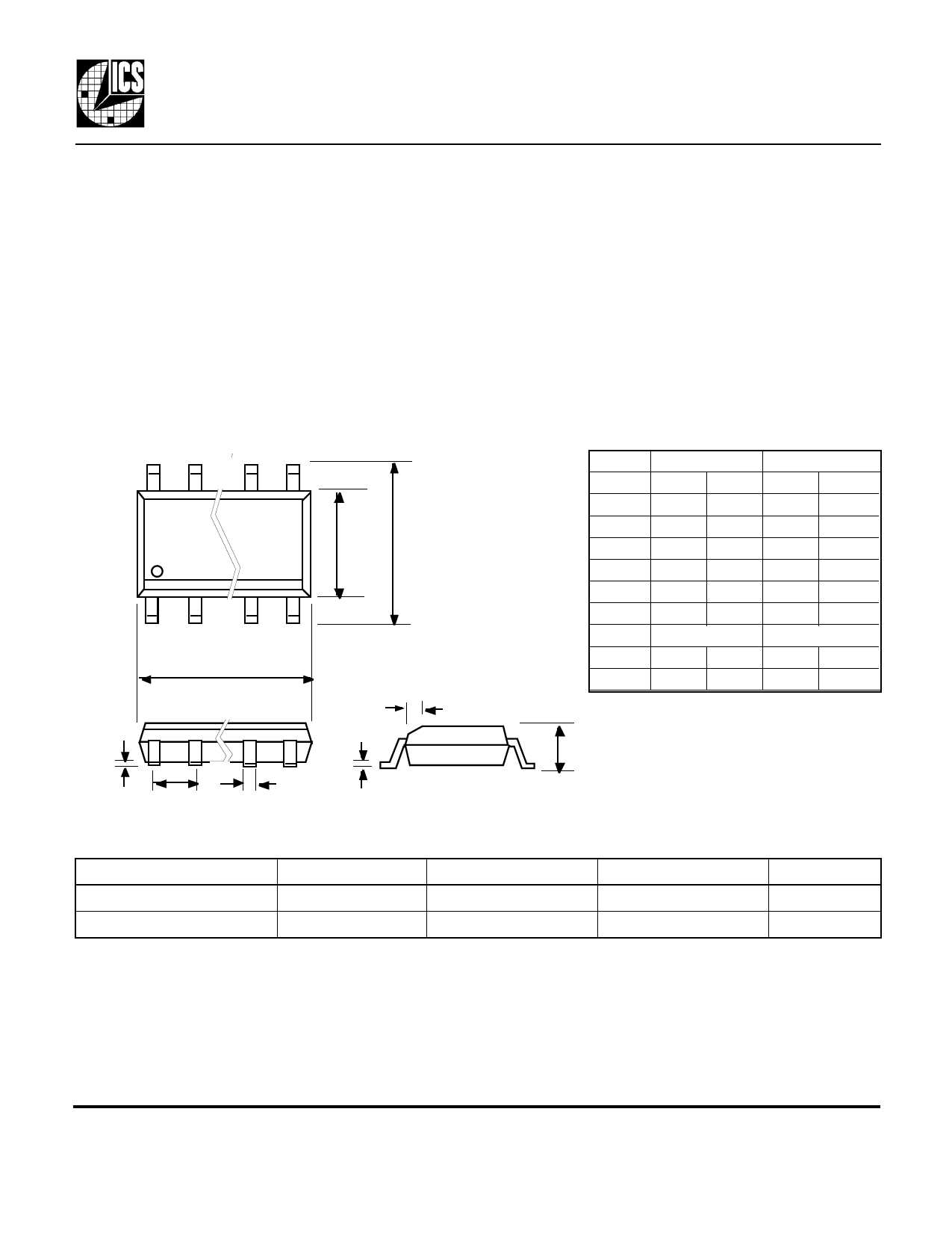
Package Outline and Package Dimensions
EH
h x 45°
D
16 pin SOIC narrow
Symbol
A
b
c
D
E
H
e
h
Q
Inches
Min Max
0.055 0.070
0.013 0.019
0.007 0.010
0.385 0.400
0.150 0.160
0.225 0.245
.050 BSC
0.016
0.004 0.01
Millimeters
Min Max
1.397 1.778
0.330 0.483
0.191 0.254
9.779 10.160
3.810 4.064
5.715 6.223
1.27 BSC
0.406
0.102 0.254
Q
e
c
b
Ordering Information
Part/Order Number
ICS614M-01
ICS614M-01T
Marking
ICS614M-01
ICS614M-01
A
Shipping packaging
tubes
tape and reel
Package
Temperature
16 pin narrow SOIC 0 to 70 C
16 pin narrow SOIC 0 to 70 C
Rev. 12308, version A . First publication, Preliminary.
Rev. 2019, version B. Added jitter, IDD specifications, showed VDDIO on pin 13, added i752 designation.
While the information presented herein has been checked for both accuracy and reliability, Integrated Circuit Systems, Incorporated (ICS) assumes no responsibility for either its
use or for the infringement of any patents or other rights of third parties, which would result from its use. No other circuits, patents, or licenses are implied. This product is
intended for use in normal commercial applications. Any other applications such as those requiring extended temperature range, high reliability, or other extraordinary
environmental requirements are not recommended without additional processing by ICS. ICS reserves the right to change any circuitry or specifications without notice. ICS does
not authorize or warrant any ICS product for use in life support devices or critical medical instruments.
MDS 614-01 B
4
Revision 020199
Printed 11/14/00
Integrated Circuit Systems • 525 Race Street • San Jose •CA•95126• (408) 295-9800tel • (408) 295-9818fax
Share Link: 