SST25VF010 View Datasheet(PDF) - Silicon Storage Technology
Part Name
Description
Manufacturer
SST25VF010 Datasheet PDF : 22 Pages
| |||
Data Sheet
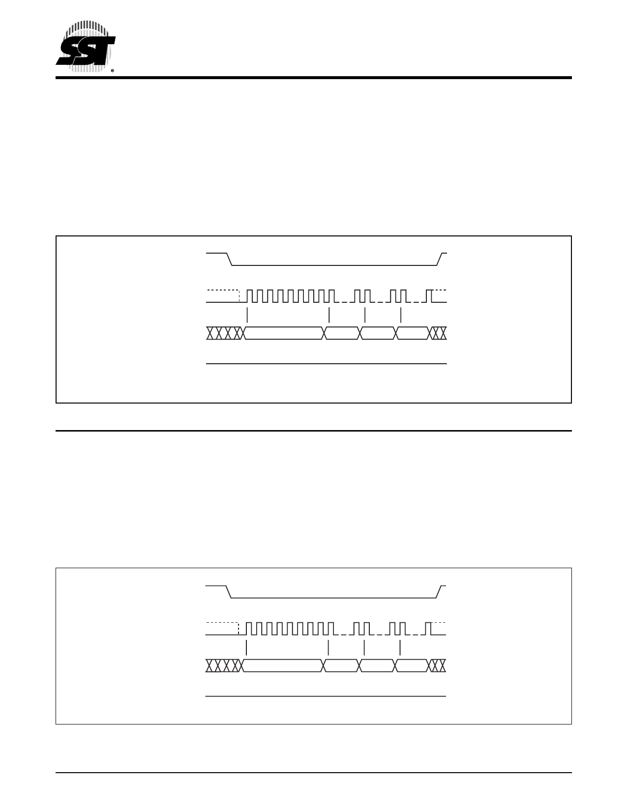
Sector-Erase
The Sector-Erase instruction clears all bits in the selected 4
KByte sector to FFH. A Sector-Erase instruction applied to
a protected memory area will be ignored. Prior to any Write
operation, the Write-Enable (WREN) instruction must be
executed. CE# must remain active low for the duration of
the any command sequence. The Sector-Erase instruction
is initiated by executing an 8-bit command, 20H, followed
by address bits [A23-A0]. Address bits [AMS-A12]
1 Mbit SPI Serial Flash
SST25VF010
(AMS = Most Significant address) are used to determine the
sector address (SAX), remaining address bits can be VIL or
VIH. CE# must be driven high before the instruction is exe-
cuted. The user may poll the Busy bit in the software status
register or wait TSE for the completion of the internal self-
timed Sector-Erase cycle. See Figure 7 for the Sector-
Erase sequence.
CE#
MODE 3
SCK MODE 0
0 1 2345 6 78
15 16
23 24 31
SI
20
ADD. ADD. ADD.
MSB
MSB
SO
HIGH IMPEDANCE
1233 F07.1
FIGURE 7: SECTOR-ERASE SEQUENCE
Block-Erase
The Block-Erase instruction clears all bits in the selected 32
KByte block to FFH. A Block-Erase instruction applied to a
protected memory area will be ignored. Prior to any Write
operation, the Write-Enable (WREN) instruction must be
executed. CE# must remain active low for the duration of
any command sequence. The Block-Erase instruction is
initiated by executing an 8-bit command, 52H, followed by
address bits [A23-A0]. Address bits [AMS-A15] (AMS = Most
significant address) are used to determine block address
(BAX), remaining address bits can be VIL or VIH. CE# must
be driven high before the instruction is executed. The user
may poll the Busy bit in the software status register or wait
TBE for the completion of the internal self-timed Block-
Erase cycle. See Figure 8 for the Block-Erase sequence.
CE#
MODE 3
SCK MODE 0
0 1 2345 6 78
15 16
23 24 31
SI
MSB
SO
FIGURE 8: BLOCK-ERASE SEQUENCE
52
ADD. ADD.
MSB
HIGH IMPEDANCE
ADD.
1233 F08.1
©2003 Silicon Storage Technology, Inc.
10
S71233-01-000
8/03
Share Link: 