STV2110A View Datasheet(PDF) - STMicroelectronics
Part Name
Description
Manufacturer
STV2110A Datasheet PDF : 15 Pages
| |||
STV2110A
Automatic Standard Identification
The circuit is alternatelyforced in eachmode during
two fields (PAL mode, SECAM mode disabled or
SECAM mode, PAL mode disabled).
If PALsignal is identified, the alternate PAL/SECAM
sequency is locked in PAL mode.
To have a SECAM identification, the circuit must
memorizes a first SECAM identification, than test
the PAL mode and confirm a second SECAM iden-
tification. The SECAM identification will take from
four to six fields.
Output Pin 21, named PS, is high level in PAL mode
and low level in SECAM mode.
Forced standard : Pin 21 can be used for the
purpose :
- Pin 21 to HVCC : PAL mode
- Pin 21 to ground : SECAM mode
VIDEO
Input Stage
The luminance input is controlled by the contrast
control stage which range is 20dB.
The luminance and color difference signals are
added in the video matrix circuit to obtain the color
signals.
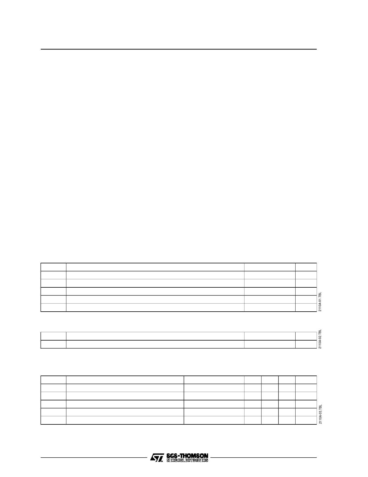
ABSOLUTE MAXIMUM RATINGS
Symbol
HVcc
Vcc
HOUT
Tstg
Toper
Parameter
Horizontal Supply Voltage (Pin 5)
Video & Chroma Supply Voltage (Pins 1-41)
Horizontal Output (Pin 15)
Storage Temperature
Operating Temperature
The color signals are sent to an RGB switch which
will drive to the outputs either internal RGB signals
or external RGB signals.
Automatic Cut-off Control
The black levels of the RGB outputs are controlled
with the cut-off loops during three line periods after
the frame retrace. The cut-off measurements are
sequentially achieved during these three lines. The
leakage current measurement is achieved during
the frame retrace and memorized on an internal
capacitor, thus the circuit is able to extract the
cut-off current from the total current measurement.
Warm-up Detector
At the start-up, the cut-off loops are switch off, a
white level is inserted on the luminance signal until
a cathode current is detected. Then the cut-off
loops are released.
RGB Inputs
To avoid the black level of the inserted signal
differing from the black level of the normal video
signal, the external RGB are clamped to the black
level of the luminance signal. Therefore, an AC
coupling is required for the RGB inputs.
The RGB inputs are controlled by a 12dB range
contrast control stage.
Value
12
HVCC + 0.5
12
-55, +150
0, +70
Unit
V
V
V
oC
oC
THERMAL DATA
Symbol
Parameter
Rth (j-a) Junction-ambient Thermal Resistance
Max.
Value
60
Unit
oC/W
DC AND AC ELECTRICAL CHARACTERISTICS
(HVCC = VCC = 9V, Tamb = 25oC unless otherwise specified)
Symbol
HVcc
Vcc
Icch
Iccv&c
PD
Parameter
Scanning Supply Voltage (Pin 5)
Video & Chroma Supply Voltage (Pins 1-41)
Scanning Supply Current (pin 5)
Video & Chroma Supply Current (Pins 1-41)
Total Power Dissipation
Test Conditions
No load
No load
No load
Min.
8.1
8.1
Typ.
9
9
25
45
630
Max.
9.9
9.9
35
55
890
Unit
V
V
mA
mA
mW
4/15
Share Link: 