T2526 View Datasheet(PDF) - Atmel Corporation
Part Name
Description
Manufacturer
T2526 Datasheet PDF : 13 Pages
| |||
1. Description
The Atmel® IC T2526 is a complete IR receiver for data communication developed and optimized for use in carrier-
frequency-modulated transmission applications. The IC offers highest sensitivity as well as highest suppression of noise
from daylight and lamps. The Atmel T2526 is available with broadest range of frequencies (30, 33, 36, 37, 38, 40, 44, 56kHz)
and 3 different noise suppression regulation types (standard, lamp, short burst) covering requirements of high-end remote
control solutions (please refer to selection guide available for Atmel T2525/T2526). Atmel The T2526 operates in a supply
voltage range of 2.7V to 5.5V.
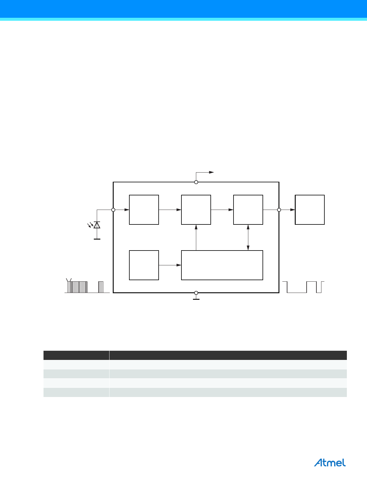
The function of the Atmel T2526 can be described using the block diagram of Figure 1-1 on page 2. The input stage meets
two main functions. First it provides a suitable bias voltage for the PIN diode. Secondly the pulsed photo-current signals are
transformed into a voltage by a special circuit which is optimized for low noise applications. After amplification by a controlled
gain amplifier (CGA) the signals have to pass a tuned integrated narrow bandpass filter with a center frequency f0 which is
equivalent to the chosen carrier frequency of the input signal The demodulator is used first to convert the input burst signal to
a digital envelope output pulse and to evaluate the signal information quality, i.e., unwanted pulses will be suppressed at the
output pin. All this is done by means of an integrated dynamic feedback circuit which varies the gain as a function of the
present environmental conditions (ambient light, modulated lamps etc.). Other special features are used to adapt to the
current application to secure best transmission quality.
Figure 1-1. Block Diagram
VS
IN
Input
CGA and
filter
Demodulator
OUT
Micro-
controller
Carrier frequency f0
Oscillator
Modulated IR signal
min 6 or 10 pulses
2. Pin Description
Table 2-1. Pin Description
Symbol
Function
VS
Supply voltage
OUT
Data output
IN
Input PIN-diode
GND
Ground
AGC/ATC
and digital control
GND
T2526
2
T2526 [DATASHEET]
4597J–AUTO–04/14
Share Link: 