QT140 View Datasheet(PDF) - Quantum Research Group
Part Name
Description
Manufacturer
QT140 Datasheet PDF : 14 Pages
| |||
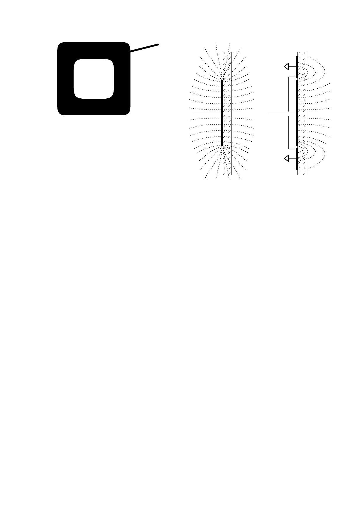
Figure 1-4 Open Electrode for Back-Illumination
Figure 1-5 Shielding Against Fringe Fields
Sense
wire
Sense
w ire
complete the return path. If the circuit ground cannot be
earth grounded by wire, for example via the supply
connections, then a ‘virtual capacitive ground’ may be
required to increase return coupling.
A ‘virtual capacitive ground’ can be created by connecting
the IC's circuit ground to:
(1) A nearby piece of metal or metallized housing;
(2) A floating conductive ground plane;
(3) A larger electronic device (to which its output might be
connected anyway).
Free-floating ground planes such as metal foils should
maximize exposed surface area in a flat plane if possible. A
square of metal foil will have little effect if it is rolled up or
crumpled into a ball. Virtual ground planes are more effective
and can be made smaller if they are physically bonded to
other surfaces, for example a wall or floor.
1.3.5 FIELD SHAPING
The electrode can be prevented from sensing in undesired
directions with the assistance of metal shielding connected
to circuit ground (Figure 1-5). For example, on flat surfaces,
the field can spread laterally and create a larger touch area
than desired. To stop field spreading, it is only necessary to
surround the touch electrode on all sides with a ring of metal
connected to circuit ground. The ring will stop field spreading
from that point outwards.
If one side of the panel to which the electrode is fixed has
moving traffic near it, these objects can cause inadvertent
detections. This is called ‘walk-by’ and is caused by the fact
that the fields radiate from either surface of the electrode
equally well. Again, shielding in the form of a metal sheet or
foil connected to circuit ground will prevent walk-by; putting
an air gap between the grounded shield and the electrode
will help to keep the value of Cx low.
1.3.6 SENSITIVITY
Sensitivity can be altered to suit various applications and
situations on a channel-by-channel basis. The easiest and
most direct way to impact sensitivity is to alter the value of
Cs; more Cs yields higher sensitivity.
1.3.6.1 Alternative Ways to Increase Sensitivity
Sensitivity can also be increased by using bigger electrodes,
reducing panel thickness, or altering panel composition.
Increasing electrode size can have diminishing returns, as
high values of Cx counteract sensor gain; however, Cs can
be increased to combat this up to the rated device limit. Also,
increasing the electrode's surface area will not substantially
increase touch sensitivity if its diameter is already much
larger in surface area than fingertip contact area.
The panel or other intervening material can be made thinner,
but again there are diminishing rewards for doing so. Panel
material can also be changed to one having a higher
dielectric constant, which will help propagate the field
through to the front. Locally adding some conductive material
to the panel (conductive materials essentially have an infinite
dielectric constant) will also help; for example, adding carbon
or metal fibers to a plastic panel will greatly increase frontal
field strength, even if the fiber density is too low to make the
plastic bulk-conductive.
1.3.6.2 Decreasing Sensitivity
In some cases the circuit may be too sensitive. Gain can be
lowered further by a number of strategies: a) making the
electrode smaller, b) making the electrode into a sparse
mesh using a high space-to-conductor ratio (Figure 1-3), or
c) by decreasing the Cs capacitors.
lQ
4
QT140/150 1.01/1102
Share Link: 