USB1T11AMTC(2008) View Datasheet(PDF) - Fairchild Semiconductor
Part Name
Description
Manufacturer
USB1T11AMTC Datasheet PDF : 11 Pages
| |||
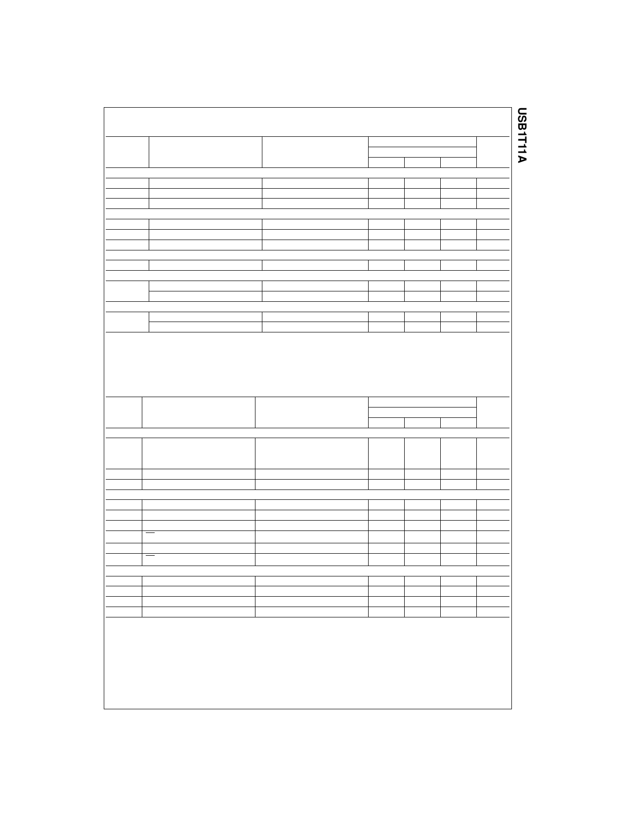
DC Electrical Characteristics Digital Pins
Over recommended range of supply voltage and operating free air temperature unless otherwise noted.
VCC = 3.0V to 3.6V.
Symbol
Parameter
Input Levels
VIL
Low-Level Input Voltage
VIH
High-Level Input Voltage
Output Levels
VOL
Low-Level Output Voltage
VOH
High-Level Output Voltage
Leakage Current
IIN
ICCFS
ICCLS
Input Leakage Current
Supply Current, Full Speed
Supply Current, Low Speed
ICCQ
Quiescent Supply Current
ICCS
Supply Current in Suspend
Conditions
IOL=4mA
IOL=20µA
IOH=4mA
IOH=20µA
VCC=3.0 to 3.6
VCC=3.0 to 3.6
VCC=3.0 to 3.6
VCC=3.0 to 3.6,
VIN=VCC or GND
VCC=3.0 to 3.6
Mode=VCC
TA=-40 to +85°C
Min. Typ. Max.
0.8
2
0.4
0.1
2.5
VCC-0.1
±5
5
5
5
10
Units
V
V
V
V
µA
mA
mA
mA
µA
DC Electrical Characteristics D+/D- Pins
Over recommended range of supply voltage and operating free air temperature unless otherwise noted.
VCC = 3.0V to 3.6V.
Symbol
Parameter
Conditions
TA=-40 to +85°C
Units
Min. Typ. Max.
Input Levels
VDI
Differential Input Sensitivity
⎪(D+) – (D-)⎪
0.2
VCM
Differential Common-Mode Range
Includes VDI Range
0.8
VSE
Single-Ended Receiver Threshold
0.8
V
2.5
V
2.0
V
Output Levels
VOL
Static Output Low-Voltage
VOH
Static Output High-Voltage
VCR
Differential Crossover
RL of 1.5kΩ to 3.6V
2.8
RL of 1.5kΩ to GND
1.3
0.3
V
3.6
V
2.0
V
Leakage Current
IOZ
High Z-State Data Line Leakage
Current
0V<VIN<3.3V
±5
µA
Capacitance
CIN(2)
Transceiver Capacitance
Capacitance Match
Pin to GND
10
pF
10
%
Output Resistance
ZDRV(3)
Driver Output Resistance
Resistance Match
Steady-State Drive
4
20
Ω
10
%
Notes:
2. This specification is guaranteed by design and statistical process distribution.
3. Excludes external resistor. To comply with USB specification 1.1, external series resistors of 24W ±1% each on
D+ and D- are recommended.
© 1999 Fairchild Semiconductor Corporation
USB1T11A • Rev. 1.0.2
5
www.fairchildsemi.com
Share Link: 