KP1040 View Datasheet(PDF) - Unspecified
Part Name
Description
Manufacturer
KP1040 Datasheet PDF : 46 Pages
| |||
KP1040
l Absolute Maximum Ratings
Parameter
Forward current
Input
Peak forward current
Reverse voltage
Power dissipation
Collector-emitter voltage
output
Emitter-collector voltage
Collector current
Collector power dissipation
Total power dissipation
Isolation voltage 1 minute
Operating temperature
Storage temperature
Soldering temperature 10 second
Symbol
It
It’;
Vi\
P’
vi ill
Vk, 0
I
PI
pi,
V
T Ir
T.
T1
Rating
50
6
70
60
6
50
150
200
5000
-30 to +lOO
-55 to +125
260
(Ta=25C)
Unit
mA
A
mW
v
v
mA
mw
mW
Vrms
C
C
C
0 Electra-optical Characteristics
Parameter
Forward voltage
Input
Peak forward voltage
Reverse current
Terminal capacitance
output Collector dark current
Current transfer ratio
Transfer
charac-
teristics
Collector-emitter saturation voltage
Isolation resistance
Floating capacitance
Cut-off frequency
Response time (Risei
Response time :FallJ
Symbol
Vi
vi ‘,I
If\
Cl
I( to
CTR
V( j \3t
Rv)
Ct
fi
tl
ti
Conditions
MIN
If = 20mA
-
lirl=O5A
-
Vb=4v
-
V=O, f=lkHz
-
vt i= 2ov
-
It =2mA, Vi -=5V
60
lF=2OmA, I( = 1mA
-
DC500V
5x10
V=O, f=lMHz
-
VI,=5V I( =2mA, R.=lOOohm
-
Vk=!XIl =2mA,R~=lOOohm --
(Ta=25C)
TYP MAX Unit
12
14
-
35
-
10
30
-
-
10
-
600
v
vI
!’ A
PF j
AI
5%
01
03
V
10
-
ohm
06
10
PF
80
-
kHz
5
20
4
20
iis ~
1’ s I
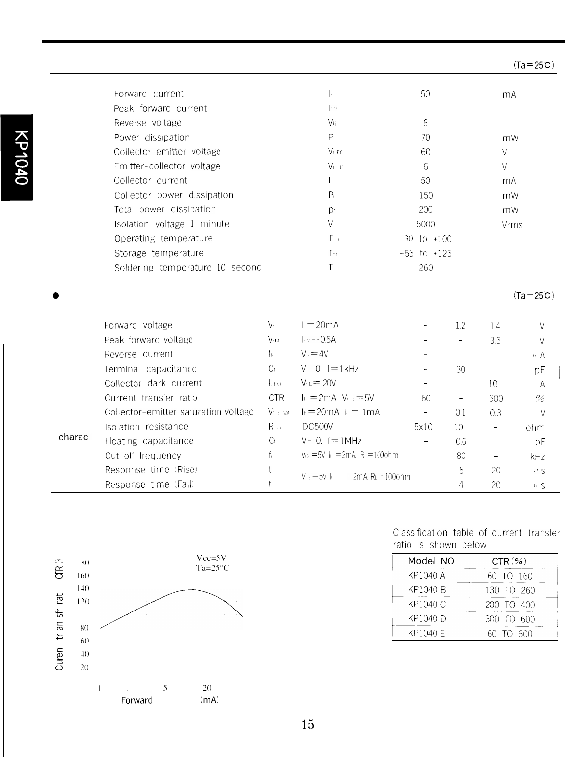
Fig. 1 Current Transfer Ratio vs.
Forward Current
‘00
acl- I x0
E0 I60
.c0-, I-40
2 130
%&J 100
5 x0
z 60
ca 10
k
2 ‘0
0
I
Vce=SV
TaSS”C
3
5 IO 70
so
Fkward current IF (mA)
15
Classification table of current transfer
ratio is shown below
Share Link: 