KP1020C View Datasheet(PDF) - Unspecified
Part Name
Description
Manufacturer
KP1020C Datasheet PDF : 46 Pages
| |||
KP1020
eAbsolute Maximum Ratings
Parameter
Forward current
Input
Peak forward current
Reverse voltage
Power dissipation
Collector-emitter voltage
I output
Emitter-collector voltage
Collector current
Collector power dissipation
Total power di;sipatlon
Isolation voltage 1 minute
Operating temperature
I
Storage temperature
I
Soldering temperature 10 second
Symbol
It
VI t 0
II
P
P’ ’
V
T /,I,
Tt
- TI
Rating
50
1
6
70
60
6
50
150
200
5000
-30 to +lOO
-55 to +125
260
0 Electra-optical Characteristics
I
I
Input
Parameter
Forward voltage
Peak forward voltage
Reverse current
Symbol
vt
VI bl
II?
Conditions
II = 20mA
Irrl-0.5A
vii = 4v
MIN l-YP
-
12
-
-
-
-
1 output
Terminal capacitance
Collector dark current
Current transfer ratio
Cl
v=o, f= 1kHz
I to vi i=2ov
CTR It = 2mA. v1 t = 5v
-
30
-
-
60
-
Collector-emitter saturation voltage vir /I II =20mA. II = 1mA
-
01
Transfer lsolatlon resistance
R >I
DC500V
5x10
10
charac- Floating capacitance
Cl
V=O, f=lMHz
-
06
teristics Cut-off frequency
fl
VI -=5V, I =2mA, R =lOOohm
-
80
Response time (Rise)
Response time (Fall)
tl
tf
V :=5V IL =2mA, R =lOOohm
-
-
5
4
(Ta=25C)
Unit
mA
A
V
mW
v
V
mA
mW
mw
Vrms
C
C
C
(Ta=25C)
MAX Unit
14
vI
35
V
10
“A 1
-
PF I
10
A
600
%
03
v’
ohm
10
PF ’
-
kHz
20
”s
20
I’ s I
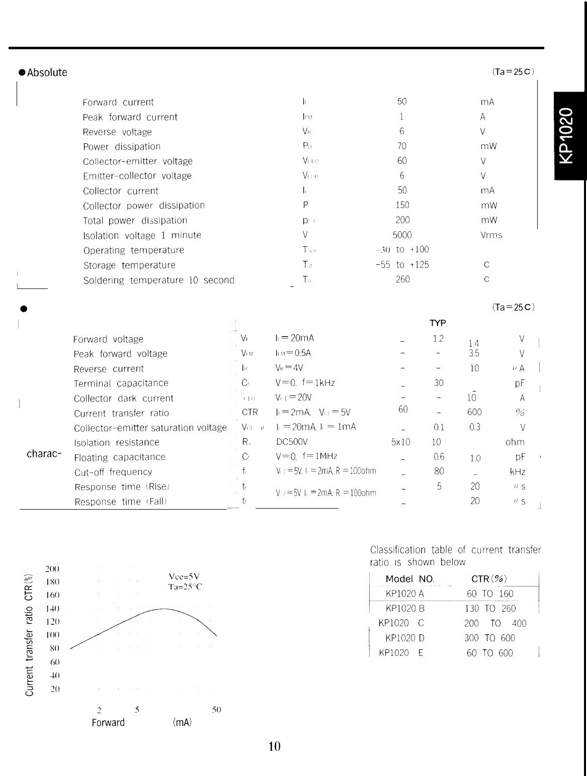
Fig. 1 Current Transfer Ratio vs.
Forward Current
Vce=SV
Ti1=35”C
Classification table of current transfer
ratio IS shown below
t-lo
40
0I
7
5 IO 20
50
F&ward current IF (mA)
10
1 KP1020 C
! KP1020 D
1 KP1020 E
200 TO 400 1
300 TO 600
60 TO 600
1
Share Link: 