ES636_09 View Datasheet(PDF) - Cyrustek corporation
Part Name
Description
Manufacturer
ES636_09 Datasheet PDF : 13 Pages
| |||
ES636
True RMS-to-DC Converters
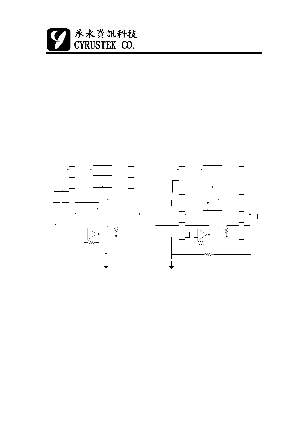
reduce the settling time and ripple is to use a post filter. Two suggested circuits are
shown in Figure 4 and Figure 5. A post filter allows a smaller CAV. With post filter,
the value of CAV should be just large enough to give the maximum dc error at the
lowest frequency of interest. And the output ripple will be removed by the post filter.
Vin
1
2
-Vs
3
Cav
+Vs + - 4
5
Vout
6
7
ABSOLUTE
VALUE
SQUARE
DIVIDER
CURRENT
MIRROR
+
BUF
-
14
+Vs Vin
1
13
2
12
-Vs
3
Cav
11
+Vs + - 4
10
5
Vout
9
6
8
7
ABSOLUTE
VALUE
SQUARE
DIVIDER
CURRENT
MIRROR
+
BUF
-
+
- C2
+
C2
10KΩ
-
14
+Vs
13
12
11
10
9
8
C3
Figure 5(a). ES636 with a One-Pole Filter
(b) with a Two-Pole Filter
Decibel Output (dB)
The dB output of the ES636 originates in the squarer/divider section and works well
over a 50dB range. The dB output has a temperature drift of 0.03dB/℃.
Frequency Response
ES636 utilizes a logarithmic circuit in performing the RMS computation of the input
signal. The bandwidth of the RMS converters is proportional to signal level. Figure 11
represent the frequency response of the converters from 35mV to 1V for ES636.
The dashed lines indicate the upper frequency limits for 1%, 10%, and ±3dB of reading
additional error. Caution must be used when designing RMS measuring systems so that
11
09/02/16
Share Link: 