MAX4295 View Datasheet(PDF) - Maxim Integrated
Part Name
Description
Manufacturer
MAX4295 Datasheet PDF : 18 Pages
| |||
Mono/Stereo 2W Switch-Mode (Class-D)
Audio Power Amplifiers
PIN
MAX4295
1, 12
2, 15
3
—
—
4, 13
5
6
7
—
—
8
—
—
9
10
11
14
—
—
16
MAX4297
10
4, 9, 16, 21
—
5
8
6, 7, 18, 19
3, 23
13
—
2
11
—
1
12
22
14
15
—
20
17
24
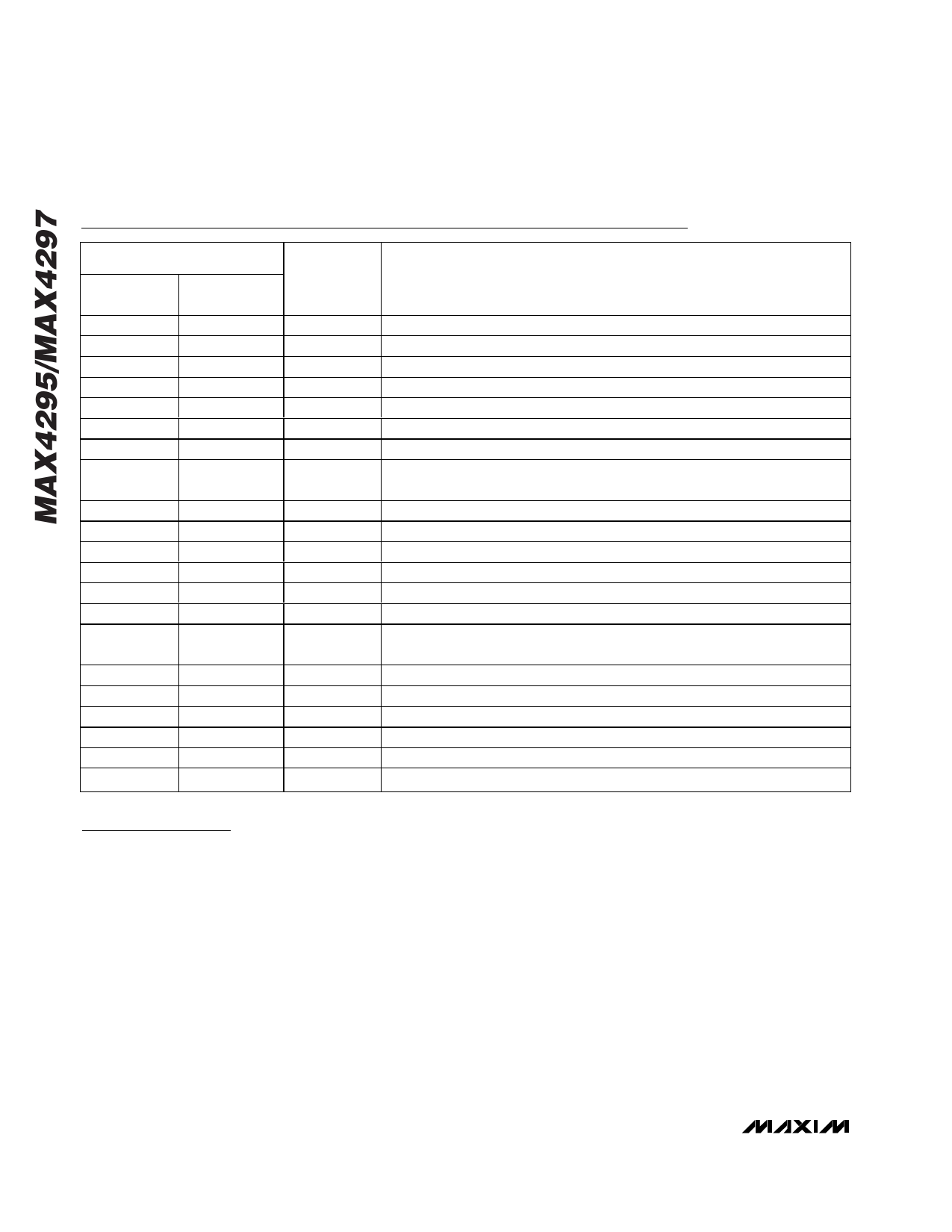
Pin Description
NAME
FUNCTION
GND
PVCC
OUT+
OUT+L
OUT+R
PGND
VCC
VCM
IN
INL
INR
AOUT
AOUTL
AOUTR
SHDN
FS1
FS2
OUT-
OUT-L
OUT-R
SS
Analog Ground
H-Bridge Power Supply
Positive H-Bridge Output
Positive Left-Channel H-Bridge Output
Positive Right-Channel H-Bridge Output
Power Ground
Analog Power Supply
Audio Input Common-Mode Voltage. Do not connect. Minimize parasitic
coupling to this pin.
Audio Input
Left-Channel Audio Input
Right-Channel Audio Input
Input Amplifier Output
Left-Channel Input Amplifier Output
Right-Channel Input Amplifier Output
Active-Low Shutdown Input. Connect to VCC for normal operation. Do not
leave floating.
Frequency Select Input 1
Frequency Select Input 2
Negative H-Bridge Output
Negative Left-Channel H-Bridge Output
Negative Right-Channel H-Bridge Output
Soft-Start
Detailed Description
The MAX4295/MAX4297 switch-mode, Class-D audio
power amplifiers are intended for portable multimedia
and general-purpose audio applications. Linear ampli-
fiers in the 1W to 2W output range are inefficient; they
overheat when operated near rated output power lev-
els. The efficiency of linear amplifiers is <50% when the
output voltage is equal to 1/2 the supply. The
MAX4295/MAX4297 Class-D amplifiers achieve effi-
ciencies of 87% or greater and are capable of deliver-
ing up to 2W of continuous maximum power to a 4Ω
load. The lost power is due mainly to the on-resistance
of the power switches and ripple current in the output.
In a Class-D amplifier, a PWM controller converts the
analog input to a variable pulse-width signal. The pulse
width is proportional to the input voltage, ideally 0% for
a 0V input signal and 100% for full-scale input voltages.
A passive lowpass LC network filters the PWM output
waveform to reconstruct the analog signal. The switch-
ing frequency is selected much higher than the maxi-
mum input frequencies so that intermodulation
products are outside the input signal bandwidth.
Higher switching frequencies also simplify the filtering
requirements.
The MAX4295/MAX4297 consist of an inverting input
operational amplifier, a PWM ramp oscillator, a con-
troller that converts the analog input to a variable pulse
width signal, and a MOSFET H-bridge power stage
(Figures 1a and 1b). The control signal is generated by
the PWM comparator; its pulse width is proportional to
the input voltage. Ideally the pulse width varies linearly
between 0% for a 0V input signal and 100% for full-
scale input voltages (Figure 2). This signal controls the
10 ______________________________________________________________________________________
Share Link: 