MAX4295 View Datasheet(PDF) - Maxim Integrated
Part Name
Description
Manufacturer
MAX4295 Datasheet PDF : 18 Pages
| |||
Mono/Stereo 2W Switch-Mode (Class-D)
Audio Power Amplifiers
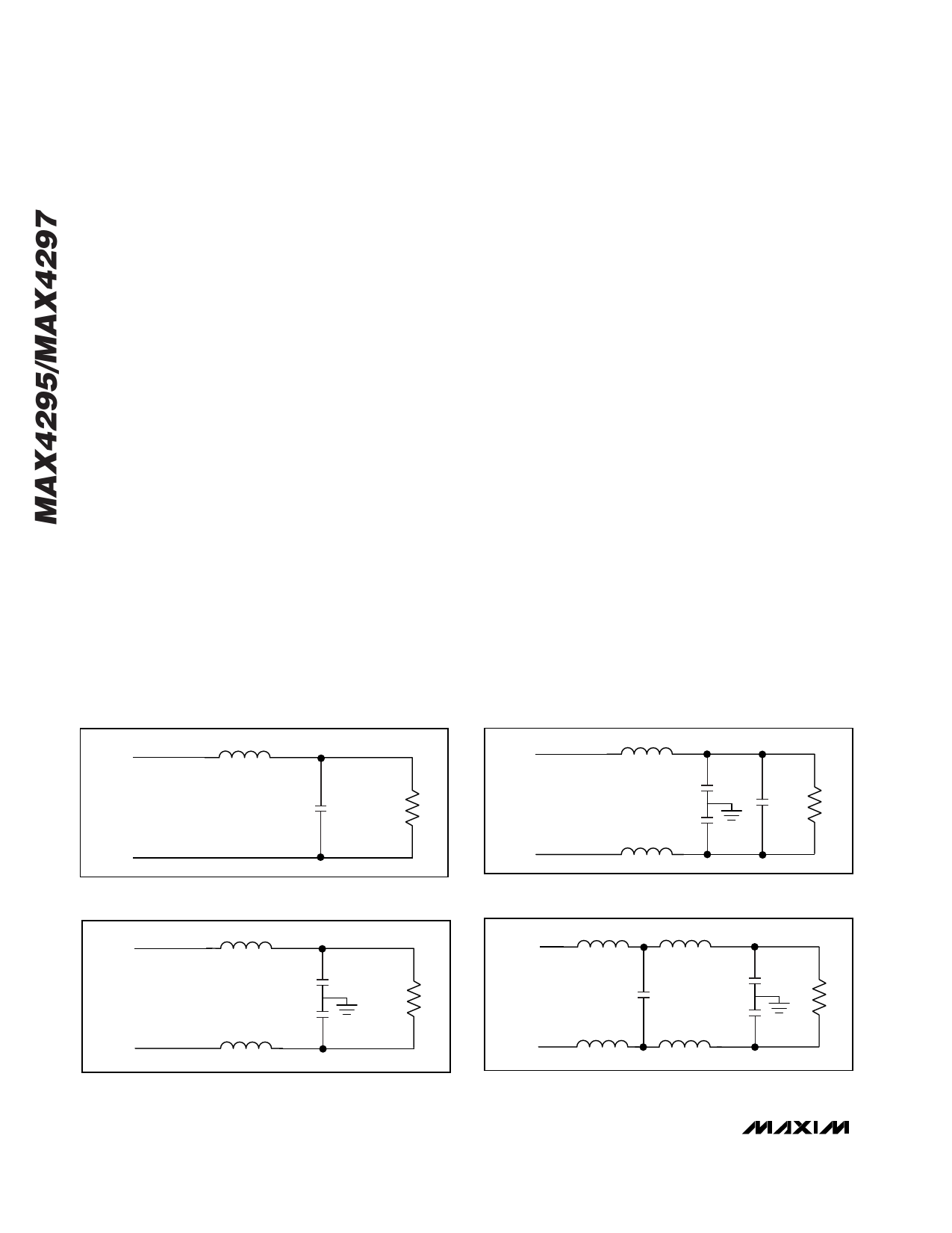
Output Filter
An output filter is required to attenuate the PWM switch-
ing frequency. Without the filter, the ripple in the load
can substantially degrade efficiency and may cause
interference problems with other electronic equipment.
A Butterworth lowpass filter is chosen for its flat pass
band and nice phase response, though other filter
implementations may also be used. Three examples
are presented below. The filter parameters for bal-
anced 2-pole (Figure 4b) and 4-pole (Figure 4d)
Butterworth filters are taken from Electronic Filter
Design Handbook by Arthur B. Williams, McGraw Hill,
Inc. These filter designs assume that the load is purely
resistive and load impedance is constant over frequen-
cy. Calculation of filter component values should
include the DC resistance of the inductors and take into
account the worst-case load scenario:
• Single Ended 2-Pole Filter (Figure 4a)
C = 1 / (√2 ✕ RL ✕ ωo), L = √2 ✕ RL / ωo
where ωo = 2 ✕ π ✕ fo (fo = filter cutoff frequency);
choosing fo = 30kHz and RL = 4Ω, C = 0.937µF, L =
30µH.
A single-ended 2-pole filter uses the minimum number
of external components, but the load (speaker) sees
the large common-mode switching voltage, which can
increase power dissipation and cause EMI problems.
• Balanced 2-Pole (Figure 4b):
A balanced 2-Pole filter does not have the common-
mode swing problem of the single-ended filter.
C = 2 / (√2 ✕ RL ✕ ωo), L = (√2 ✕ RL)/(2 ✕ ωo); choosing
fo = 30kHz and RL = 4Ω, C1a = C1b = 2.0µF, L1a =
L1b = 15µH.
A single capacitor connected across RL, with a value of
CL = 1/(√2 ✕ RL ✕ ωo), can be used in place of C1a and
C1b. However, the configuration as shown gives an
improved rejection to common-mode signal compo-
nents of OUT+_ and OUT-_. If the single capacitor
scheme is used, additional capacitors (Ca and Cb) can
be added from each side of RL, providing a high-fre-
quency short to ground (Figure 4c). These capacitors
should be approximately 0.2 ✕ CL.
• Balanced 4-Pole Filter (Figure 4d)
A balanced 4-pole filter is more effective in suppress-
ing the switching frequency and its harmonics.
For the 4-pole Butterworth filter, the normalized values
are: L1N = 1.5307, L2N = 1.0824, C1N = 1.5772, C2N =
0.3827.
The actual inductance and capacitance values for fo =
30kHz and a bridge-tied load of RL = 4Ω are given by:
L1 = (L1N ✕ RL ) / (2 ✕ ωo) = 16.24µH, L2 = (L2N ✕ RL) /
(2 ✕ ωo) = 11.5µH, C1 = C1N / (RL ✕ ωo) = 2.1µF, C2a =
C2b = (2 ✕ C2N) / (RL ✕ ωo) = 1.0µF.
L
OUT+
C
RL
OUT-
Figure 4a. Single-Ended 2-Pole Filter
L1
OUT+
Ca
CL
RL
Cb
OUT-
L2
Figure 4c. Alternate Balanced 2-Pole Filter
L1
OUT+
C1a
RL
C1b
OUT-
L2
Figure 4b. Balanced 2-Pole Filter
L1a
L2a
OUT+
C2a
C1
RL
C2b
OUT-
L1b
L2b
Figure 4d. Balanced 4-Pole Filter
14 ______________________________________________________________________________________
Share Link: 