MAX44007(2010) View Datasheet(PDF) - Maxim Integrated
Part Name
Description
Manufacturer
MAX44007 Datasheet PDF : 21 Pages
| |||
Low-Power Digital Ambient Light Sensor
with Enhanced Sensitivity
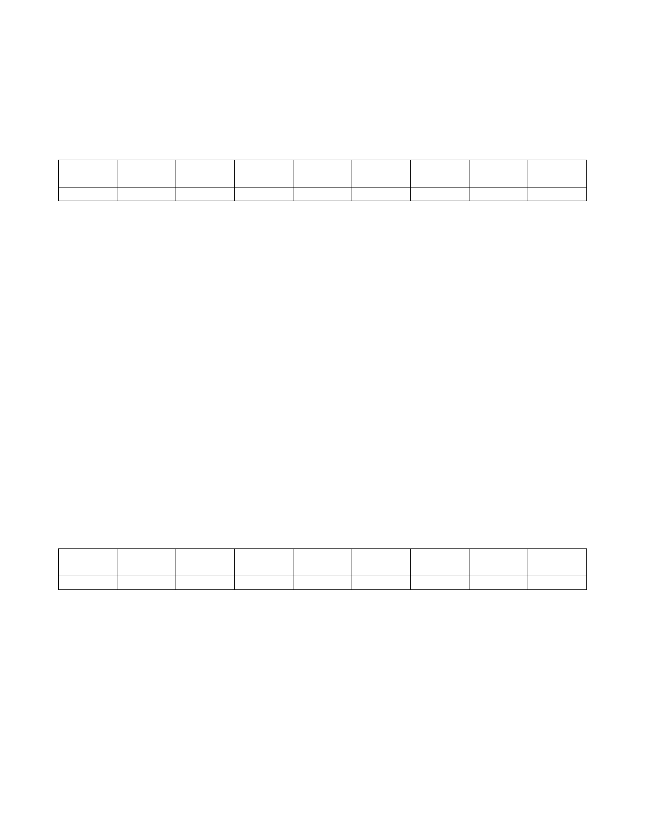
Lux Low-Byte Register 0x04
BIT 7
—
BIT 6
—
BIT 5
—
BIT 4
—
BIT 3
M3
BIT 2
M2
BIT 1
M1
BIT 0
M0
REGISTER
ADDRESS
0x04
Bits in Lux Low-Byte register 0x04 give the 4 least significant bits of the mantissa byte representing the lux reading
of ambient light. Combined with the Lux High-Byte register 0x03, it extends the resolution and dynamic range of lux
measurements of the IC.
E3–E0: Exponent bits of lux reading
M7–M0: Mantissa byte of lux reading
Lux = 2(exponent) x mantissa x 0.025
Exponent = 8xE3 + 4xE2 + 2xE1 + E0
Mantissa = 128xM7 + 64xM6 + 32xM5 + 16xM4 + 8xM3 + 4xM2 + 2xM1 + M0
Combining contents of register 0x03 and 0x04:
A code of 0000 0000 0001 calculates to be 0.025 lux.
A code of 0000 0001 0000 calculates to be 0.04 lux.
A code of 0001 0001 0001 calculates to be 0.425 lux.
A code of 1110 1111 1111 calculates to be 104,448 lux.
A code of 1110 1111 1110 calculates to be 104,038 lux.
The Lux High-Byte 0x03 and Lux Low-Byte 0x04 register updates are internally disabled at the start of a valid address
transmission from the master. Updating reinitiates at the next valid STOP condition. This prevents erroneous readings,
in the event an update occurs between readings of registers 0x03 and 0x04.
Update of the contents of this register is internally disabled during I2C read operations to ensure proper data transfer
between internal ADC and I2C registers. Update of I2C registers is resumed when the master sends a STOP command.
If the user wants to read both the Lux High-Byte register 0x03 and Lux Low-Byte register 0x04, then the master should
not send a STOP command between the reads of the two registers. Instead a REAPEATED START command should
be used. This ensures accurate data is obtained from the I2C registers (by disabling internal updates during the read
process).
Upper Threshold High-Byte Register 0x05
BIT 7
UE3
BIT 6
UE2
BIT 5
UE1
BIT 4
UE0
BIT 3
UM7
BIT 2
UM6
BIT 1
UM5
BIT 0
UM4
REGISTER
ADDRESS
0x05
The Upper Threshold register exponent with the four most significant bits of the mantissa sets the upper trip level for
interrupt functionality. This upper limit is relevant only if the INTE bit in the interrupt enable register is set. If the lux level
is greater than this light level for a time greater than that specified in the Threshold Timer register, the INTS bit in the
Status register is set and the INT pin is pulled low.
Mantissa (UM[7:4]): Four most significant bits of mantissa upper threshold
Exponent (UE[3:0]): Exponent bits upper threshold
Upper lux threshold = 2(exponent) x mantissa x 0.025
Exponent = 8xUE3 + 4xUE2 + 2xUE1 + UE0
Mantissa = 128xUM7+ 64xUM6+ 32xUM5 + 16xUM4 +15
11
Share Link: 