SI3208-X-FM View Datasheet(PDF) - Silicon Laboratories
Part Name
Description
Manufacturer
SI3208-X-FM Datasheet PDF : 38 Pages
| |||
Si3226/7
Si3208/9
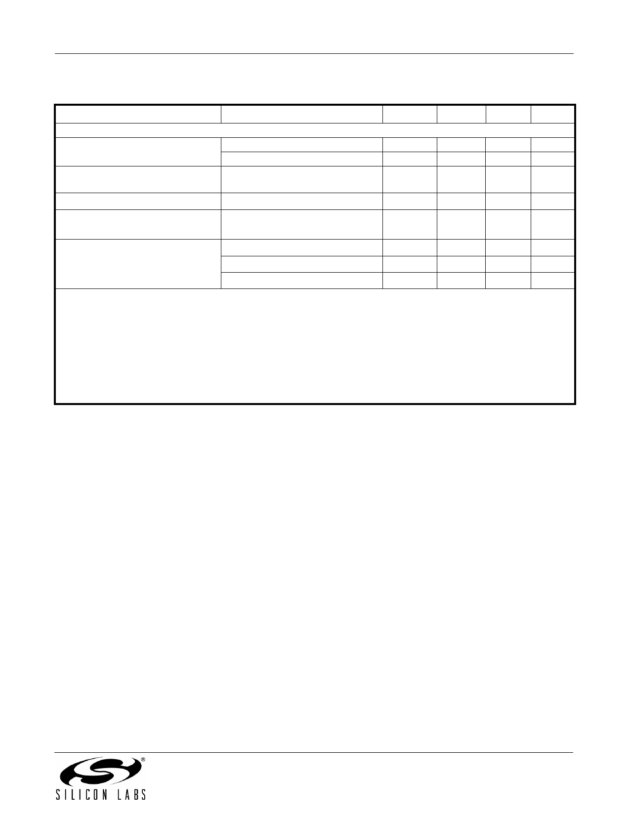
Table 4. AC Characteristics (Continued)
(VDD = 3.13 to 3.47 V, TA = 0 to 70 °C for F-Grade, –40 to 85 °C for G-Grade)
Parameter
Test Condition
Min
Typ
Max Unit
Longitudinal Performance
Longitudinal to Metallic/PCM
200 Hz to 1 kHz
58
Balance (forward or reverse)
1 kHz to 3.4 kHz
53
Metallic/PCM to Longitudinal Bal-
200 Hz to 3.4 kHz
40
ance
Longitudinal Impedance
200 Hz to 3.4 kHz at TIP or RING
—
60
—
dB
58
—
dB
—
—
dB
50
—
Ω
Longitudinal Current per Pin
Active off-hook
200 Hz to 3.4 kHz
—
—
30
mA
DC Current
Differential
—
—
45
mA
Common Mode
—
—
30
mA
Differential + Common Mode
—
—
45
mA
Notes:
1. The input signal level should be 0 dBm0 for frequencies greater than 100 Hz. For 100 Hz and below, the level should
be –10 dBm0. The output signal magnitude at any other frequency is smaller than the maximum value specified.
2. Analog signal measured as VTIP – VRING. Assumes ideal line impedance matching.
3. The quantization errors inherent in the µ/A-law companding process can generate slightly worse gain tracking
performance in the signal range of 3 to –37 dB for signal frequencies that are integer divisors of the 8 kHz PCM
sampling rate.
4. VDD1–VDD4 = 3.3 V, VBAT = –52 V, no fuse resistors; RL = 600 Ω, ZS = 600 Ω synthesized using RS register
coefficients.
5. The level of any unwanted tones within the bandwidth of 0 to 4 kHz does not exceed –55 dBm.
Preliminary Rev. 0.33
7
Share Link: 