AS5040 View Datasheet(PDF) - Unspecified
Part Name
Description
Manufacturer
AS5040 Datasheet PDF : 20 Pages
| |||
AS5040 10-BIT PROGRAMMABLE MAGNETIC ROTARY ENCODER
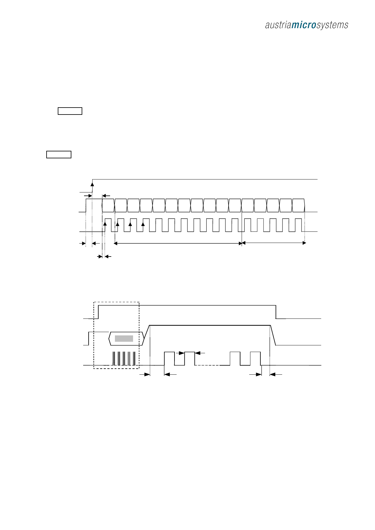
Programming the AS5040
After power-on, programming the AS5040 is enabled at
the rising edge of CSn with Prog = logic high. 16 bit
configuration data must be serially written into the OTP
register via the Prog-pin. The first “CCW” bit is followed
by the zero position data (MSB first) and the Incremental
Mode setting. Data must be valid at the rising edge of
CLK (Figure 11).
After writing the data into the OTP register it can be
permanently programmed (“zapped”) by rising the Prog
pin to the programming voltage VPROG. 16 accurate CLK
pulses (tPROG) must be applied to program the fuses
(Figure 12). The programmed data is available after the
next power-on.
OTP Register Content:
CCW
Counter Clockwise Bit
CCW=0 – angular value increases in clockwise direction
CCW=1 - angular value increases in counter clockwise
direction
Z [9:0]
Programmable Zero / Index Position
Indx
Index Pulse Width Selection
Div1,Div0 Divider Setting of Incremental Output
Md1, Md0 Incremental Output Mode Selection
CSn
Prog
t Data in
CCW Z9 Z8 Z7 Z6 Z5 Z4 Z3 Z2 Z1 Z0 Indx Div1 Div0 Md1 Md0
CLKPROG
1
t Prog enable
t Data in valid
Zero / Index Position
16
Incremental Modes
Figure 11: Programming Access – Write Data
CSn
W rite D a ta
P ro g
C LK PROG
D a ta
P ro g ra m m in g M o d e
V PROG
P o w e r O ff
t PROG
1
16
t Load PRO G
t P R O G fin is h e d
Figure 12: Programming Access – Zapp Data
Zero Position Programming
Any 10bit angular position can be defined as the
zero/index position. It may be used in several
applications in order to simplify assembly. For Zero
Position Programming, the magnet must be brought to
the mechanical zero position of the system (e.g. the “off”-
position of a rotary switch). The orientation (north/south
pole) of the magnet does not need to be considered.
The mechanical zero position can be read out via the SSI
and be assigned as new zero position Z[9:0] and
programmed into the OTP register.
This new absolute zero position at the same time also
represents the Index pulse position for incremental
output modes.
Revision 1.1
www.austriamicrosystems.com
Page 9 of 20
Share Link: 