2SA2058(2001) View Datasheet(PDF) - Toshiba
Part Name
Description
Manufacturer
2SA2058 Datasheet PDF : 5 Pages
| |||
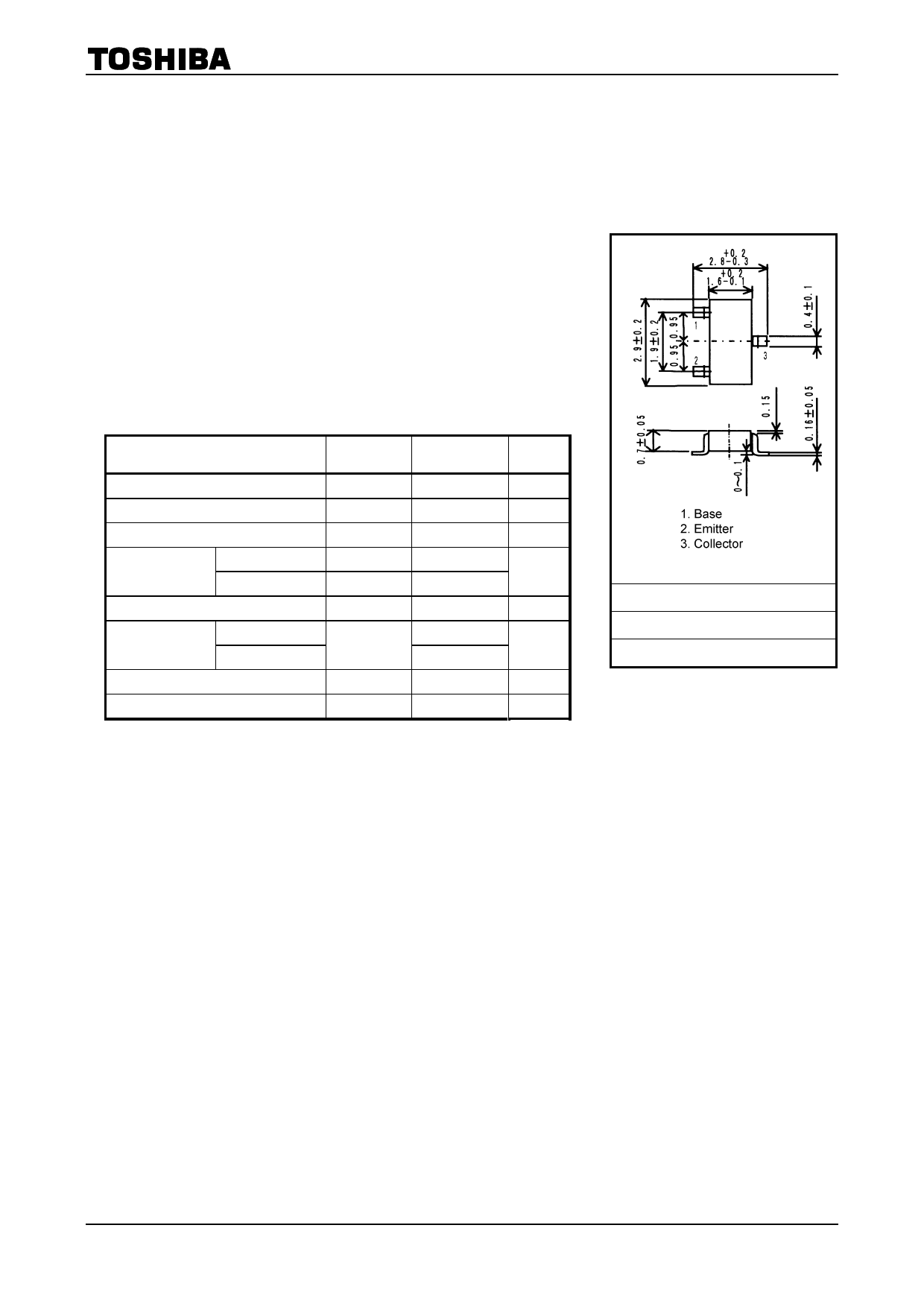
TOSHIBA Transistor Silicon PNP Epitaxial Type
2SA2058
High-Speed Switching Applications
DC-DC Converter Applications
Strobe Applications
2SA2058
Unit: mm
• High DC current gain: hFE = 200 to 500 (IC = −0.2 A)
• Low collector-emitter saturation voltage: VCE (sat) = −0.19 V (max)
• High-speed switching: tf = 25 ns (typ.)
Maximum Ratings (Ta = 25°C)
Characteristics
Symbol
Rating
Unit
Collector-base voltage
Collector-emitter voltage
Emitter-base voltage
Collector current
DC
Pulse
Base current
Collector power
dissipation
DC
t = 10 s
Junction temperature
Storage temperature range
VCBO
−20
V
VCEO
−10
V
VEBO
IC
ICP
IB
−7
V
−1.5
A
−2.5
−150
mA
PC
500
mW
(Note)
750
Tj
150
°C
Tstg
−55 to 150
°C
Note: Mounted on FR4 board (glass epoxy, 1.6 mm thick, Cu area:
645 mm2)
JEDEC
―
JEITA
―
TOSHIBA
2-3S1A
Weight: 0.01 g (typ.)
Electrical Characteristics (Ta = 25°C)
Characteristics
Collector cut-off current
Emitter cut-off current
Collector-emitter breakdown voltage
DC current gain
Collector-emitter saturation voltage
Base-emitter saturation voltage
Collector output capacitance
Rise time
Switching time
Storage time
Fall time
Symbol
Test Condition
ICBO
IEBO
V (BR) CEO
hFE (1)
hFE (2)
VCE (sat)
VBE (sat)
Cob
tr
tstg
tf
VCB = −20 V, IE = 0
VEB = −7 V, IC = 0
IC = −10 mA, IB = 0
VCE = −2 V, IC = −0.2 A
VCE = −2 V, IC = −0.6 A
IC = −0.6 A, IB = −20 mA
IC = −0.6 A, IB = −20 mA
VCB = −10 V, IE = 0, f = 1 MHz
See Figure 1 circuit diagram.
VCC ∼− −6 V, RL = 10 Ω
−IB1 = IB2 = −20 mA
Min Typ. Max Unit
−100 nA
−100 nA
−10
V
200
500
125
−0.19 V
−1.10 V
12
pF
50
115
ns
25
1
2001-10-29
Share Link: 