74AHC2G241 View Datasheet(PDF) - Philips Electronics
Part Name
Description
Manufacturer
74AHC2G241 Datasheet PDF : 19 Pages
| |||
Philips Semiconductors
74AHC2G241; 74AHCT2G241
Dual buffer/line driver; 3-state
Table 11: Dynamic characteristics type 74AHCT2G241 …continued
GND = 0 V; tr = tf ≤ 3.0 ns; see Figure 7
Symbol Parameter
Conditions
tPZH, tPZL enable time 1OE to 1Y
enable time 2OE to 2Y
tPHZ, tPLZ disable time 1OE to 1Y
disable time 2OE to 2Y
see Figure 5; VCC = 4.5 V to 5.5 V
CL = 15 pF
CL = 50 pF
see Figure 6; VCC = 4.5 V to 5.5 V
CL = 15 pF
CL = 50 pF
see Figure 5; VCC = 4.5 V to 5.5 V
CL = 15 pF
CL = 50 pF
see Figure 6; VCC = 4.5 V to 5.5 V
CL = 15 pF
CL = 50 pF
[1] All typical values are measured at VCC = 5.0 V.
13. Waveforms
Min
Typ
Max
Unit
1.0
-
1.0
-
6.5
ns
9.5
ns
1.0
-
1.0
-
6.5
ns
9.5
ns
1.0
-
1.0
-
8.5
ns
11.0
ns
1.0
-
1.0
-
8.5
ns
11.0
ns
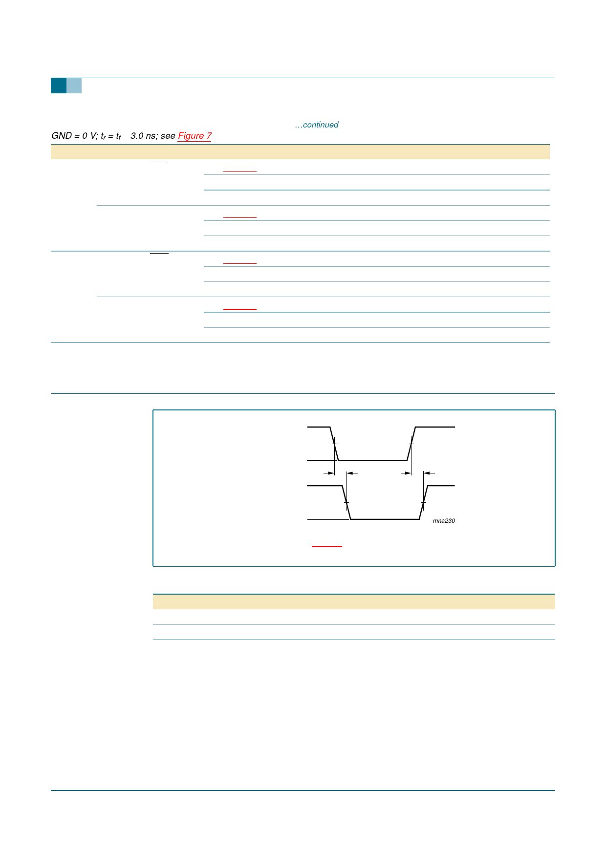
VI
nA input
GND
VOH
nY output
VOL
VM
tPHL
VM
Measurement points are given in Table 12.
Fig 4. The input (nA) to output (nY) propagation delays.
Table 12: Measurement points
Type
74AHC2G241
VI input requirements VM input
GND to VCC
50 % VCC
74AHCT2G241
GND to 3.0 V
1.5 V
tPLH
mna230
VM output
50 % VCC
50 % VCC
9397 750 12887
Product data sheet
Rev. 01 — 10 March 2004
© Koninklijke Philips Electronics N.V. 2004. All rights reserved.
12 of 19
Share Link: 