74F148 View Datasheet(PDF) - Philips Electronics
Part Name
Description
Manufacturer
74F148 Datasheet PDF : 10 Pages
| |||
Philips Semiconductors
8-input priority encoder
Product specification
74F148
FEATURES
• Code conversions
• Multi-channel D/A converter
• Decimal-to-BCD converter
• Cascading for priority encoding of “N” bits
• Input enable capability
• Priority encoding-automatic selection of highest priority input line
• Output enable-active Low when all inputs are High
• Group signal output-active when any input is Low
DESCRIPTION
The 74F148 8-input priority encoder accepts data from eight
active-Low inputs and provides a binary representation on the three
active-Low outputs. A priority is assigned to each input so that when
two or more inputs are simultaneously active, the input with the
highest priority is represented on the output, with input line I7 having
the highest priority. A High on the Enable Input (EI) will force all
outputs to the inactive (High) state and allow new data to settle
without producing erroneous information at the outputs. A Group
Signal (GS) output and an Enable Output (EO) are provided with the
three data outputs. The GS is active-Low when any input is Low:
this indicates when any input is active. The EO is active-Low when
all inputs are High. Using the Enable Output along with the Enable
Input allows priority encoding of N input signals. Both EO and GS
are active-High when the Enable Input is High.
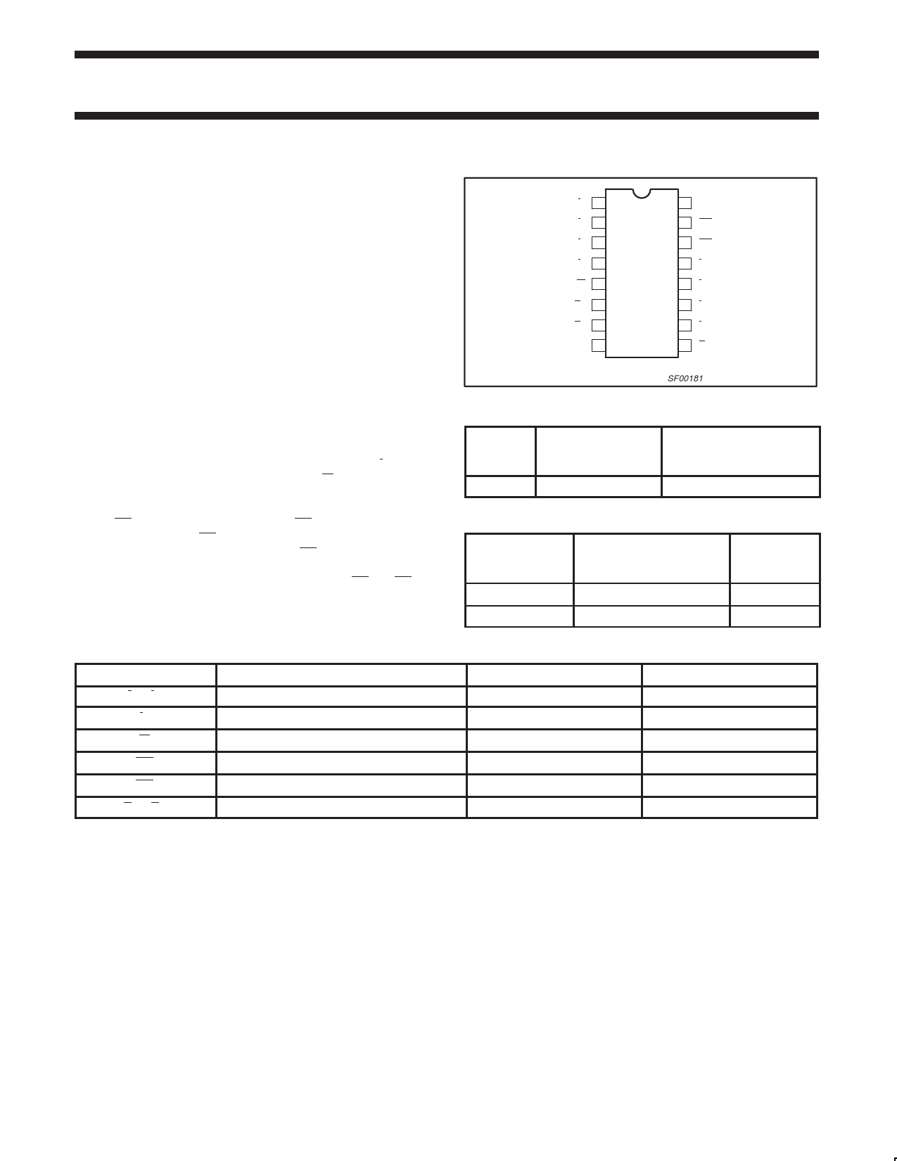
PIN CONFIGURATION
I4 1
I5 2
I6 3
I7 4
EI 5
A2 6
A1 7
GND 8
16 VCC
15 EO
14 GS
13 I3
12 I2
11 I1
10 I0
9 A0
SF00181
TYPE
74F148
TYPICAL
PROPAGATION
DELAY
6.0ns
TYPICAL
SUPPLY CURRENT
(TOTAL)
23mA
ORDERING INFORMATION
DESCRIPTION
COMMERCIAL RANGE
VCC = 5V ±10%,
Tamb = 0°C to +70°C
16-pin plastic DIP
N74F148N
16-pin plastic SO
N74F148D
PKG DWG #
SOT38-4
SOT109-1
INPUT AND OUTPUT LOADING AND FAN-OUT TABLE
PINS
DESCRIPTION
74F (U.L.) HIGH/LOW
I1 – I7
Priority inputs (active Low)
1.0/2.0
I0
Priority input (active Low)
1.0/1.0
EI
Enable input (active Low)
1.0/2.0
EO
Enable output (active Low)
50/33
GS
Group select output (active Low)
50/33
A0 – A2
Address outputs (active Low)
50/33
NOTE: One (1.0) FAST unit load is defined as: 20µA in the High state and 0.6mA in the Low state.
LOAD VALUE HIGH/LOW
20µA/1.2mA
20µA/0.6mA
20µA/1.2mA
1.0mA/20mA
1.0mA/20mA
1.0mA/20mA
March 1, 1990
2
853–0345 98994
Share Link: 