74LV688D View Datasheet(PDF) - Philips Electronics
Part Name
Description
Manufacturer
74LV688D Datasheet PDF : 12 Pages
| |||
Philips Semiconductors
8-bit magnitude comparator
Product specification
74LV688
AC CHARACTERISTICS
GND = 0V; tr = tf = 2.5ns; CL = 50pF; RL = 1KΩ
SYMBOL
PARAMETER
WAVEFORM
CONDITION
VCC(V)
1.2
tPHL/tPLH
Propagation delay
Pn, Qn to P=Q
2.0
2
2.7
3.0 to 3.6
4.5 to 5.5
1.2
tPHL/tPLH
Propagation delay
E to P=Q
2.0
1
2.7
3.0 to 3.6
4.5 to 5.5
NOTES:
1. Unless otherwise stated, all typical values are at Tamb = 25°C.
2. Typical value measured at VCC = 3.3V.
3. Typical value measured at VCC = 5.0V.
LIMITS
–40 to +85 °C
MIN
TYP1
MAX
100
–
28
45
20
32
162
26
112
18
50
–
17
29
13
21
102
17
72
12
–40 to +125 °C
MIN MAX
–
57
40
33
22
–
38
27
22
15
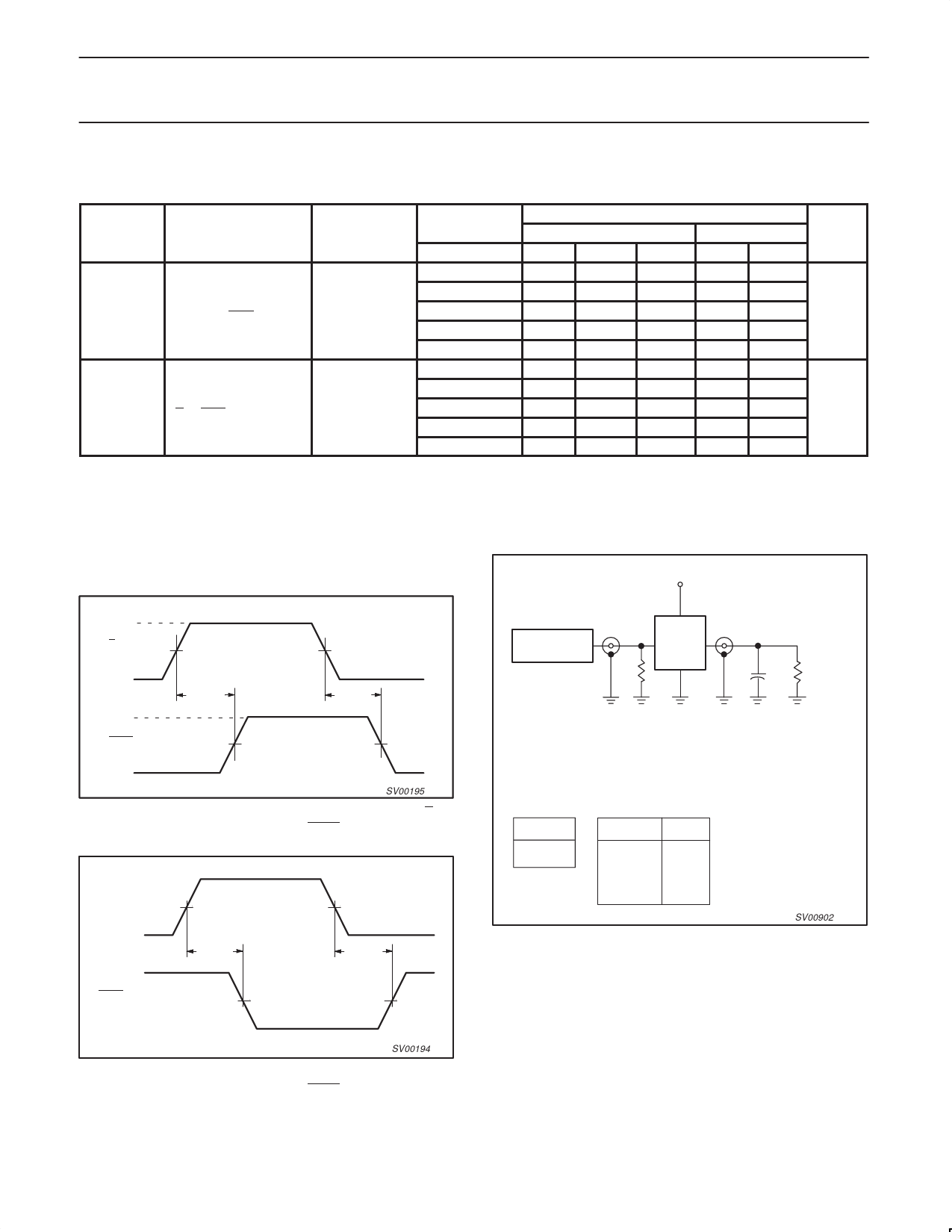
AC WAVEFORMS
TEST CIRCUIT
VM = 1.5V at VCC w 2.7V; VM = 0.5 VCC at VCC t 2.7V.
VOL and VOH are the typical output voltage drop that occur with the
Vcc
output load.
UNIT
ns
ns
VI
E INPUT
VM
GND
VOH
tPLH
tPHL
P = Q OUTPUT
VM
VOL
Waveform 1.
SV00195
Propagation delays from the enable input (E) to
the equal-to output (P = Q).
Pn, Qn INPUT
VM
tPHL
VM
tPLH
PULSE
GENERATOR
Vl
RT
D.U.T.
VO
50pF
CL
RL= 1k
Test Circuit for Outputs
DEFINITIONS
RL = Load resistor
CL = Load capacitance includes jig and probe capacitiance
RT = Termination resistance should be equal to ZOUT of pulse generators.
TEST
tPLH/tPHL
VCC
< 2.7V
2.7–3.6V
≥ 4.5 V
VI
VCC
2.7V
VCC
SV00902
Waveform 3. Load circuitry for switching times
P = Q OUTPUT
VM
VM
SV00194
Waveform 2. Propagation delays from the inputs (Pn, Qn) to
the equal-to output (P = Q).
1998 Jun 23
6
Share Link: 