81C55 View Datasheet(PDF) - Oki Electric Industry
Part Name
Description
Manufacturer
81C55 Datasheet PDF : 19 Pages
| |||
¡ Semiconductor
MSM81C55-5RS/GS/JS
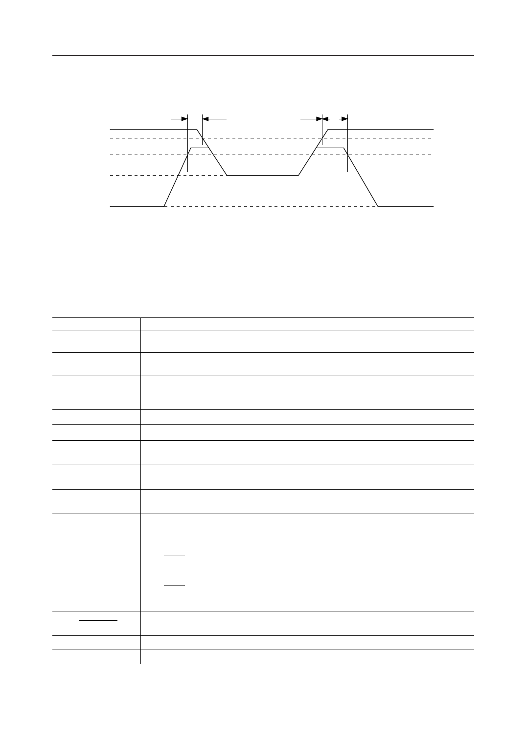
(2) Method using RESET
5 V VCC
4.5 V
2.2 V
VCCH
tSU
tR
Standby Mode
RESET
GND
Note: In this case, the C/S register is reset, the port is set into the input mode, and the timer stops.
PIN FUNCTION
Symbol
RESET
ALE
AD0 - 7
CE
IO/M
RD
WR
PA0 - 7
(PB0 - 7)
PC0 - 5
TIMER IN
TIMER OUT
VCC
GND
Function
A high level input to this pin resets the chip, places all three I/O ports in the input mode, resets all
output latches and stops timer.
Negative going edge of the ALE (Address Latch Enable) input latches AD0 - 7, IO/M, and CE signals into
the respective latches.
Three-state, bi-directional address/data bus. Eight-bit address information on this bus is read into
the internal address latch at the negative going edge of the ALE. Eight bits of data can be read from
or written to the chip using this bus depending on the state of the WRITE or READ input.
When the CE input is high, both read and write operations to the chip are disabled.
A high level input to this pin selects the internal I/O functions, and a low level selects the memory.
If this pin is low, data from either the memory or ports is read onto the AD0 - 7 lines depending on
the state of the IO/M line.
If this pin is low, data on lines AD0 - 7 is written into either the memory or into the selected port
depending on the state of the line IO/M line.
General-purpose I/O pins. Input/output directions can be determined by programming the command/
status (C/S) register.
Three pins are usable either as general-purpose I/O pins or control pins for the PA and PB ports.
When used as control pins, they are assigned to the following functions:
PC0: A INTR (port A interrupt)
PC1: A BF (port A full)
PC2: A STB (port A strobe)
PC3: B INTR (port B interrupt)
PC4: B BF (port B buffer full)
PC5: B STB (port B strobe)
Input to the counter/timer
Timer output. When the present count is reached during timer operation, this pin provides
a square-wave or pulse output depending on the programmed control status.
3–6V power supply
GND
9/19
Share Link: 