AB-12 View Datasheet(PDF) - Fairchild Semiconductor
Part Name
Description
Manufacturer
AB-12 Datasheet PDF : 4 Pages
| |||
AB-12
APPLICATION BULLETIN
Inspection of this figure shows that the maximum current
that the inductor ever sees consists of the DC current, plus
half of the peak-to-peak current due to the switching. This
latter is called the ripple current. Using the equation above,
we can calculate this peak current as:
IPK
=
IDC
+
-I--P---P-
2
=
IDC
+
1-- -(--V----i--n----–----V-----o---u--t--)----´----t--o---n-
2
L
=
IDC
+
12--
-(--V----i--n----–----V-----o---u--t--)----´----T------´----D-----C---
L
where ton is the time that the converter is in State 1, T is the
switching period (one over the switching frequency) and DC
is the Duty Cycle, that is, the percentage of time that the con-
verter is in State 1.
Caveat: This calculation has assumed that the voltage drops
due to the various components (such as the resistive drop of
the MOSFETs and inductor or current sense resistor, or the
forward voltage of a schottky in a non-synchronous con-
verter) are negligible compared to the input and output volt-
ages. If they are not, use these more accurate equations
instead:
Synchronous Converter:
IPK
=
ID
C
+
12--
(---V----i--n----–----V-----o---u--t---–-----I---´-----R----)-
L
(---V----o---u---t---+-----I---´-----R----)-
Vin
T
Nonsynchronous Converter:
IPK
=
ID
C
+
1--
2
(---V----i--n----–----V-----o---u--t---–-----I---´-----R----)-
L
(-(--V-V---o-i--nu---t-–--+--I---I-´--´--R---R--M--S---+-+----V-V----f-f-)-)
T
where Rs is the sum of the sense resistor’s resistance and the
winding resistance of the inductor, Vf is the forward drop of
the schottky, and R is the sum of the resistance of Rs and the
on-resistance of the MOSFET, R = Rs + RM.
Inductor Core Saturation
Having now calculated the peak inductor current, we can
look at what this does to the inductor. The fundamental fact
to know is that as the current through an inductor increases,
its inductance decreases. This is due to the underlying phys-
ics of the core material. How much the inductance decreases
is the important question: if it decreases too much, the con-
verter may not work properly any more. The current at which
the inductor does not function properly in the circuit any
more is called the “saturation current”, and is a fundamental
parameter of the inductor.
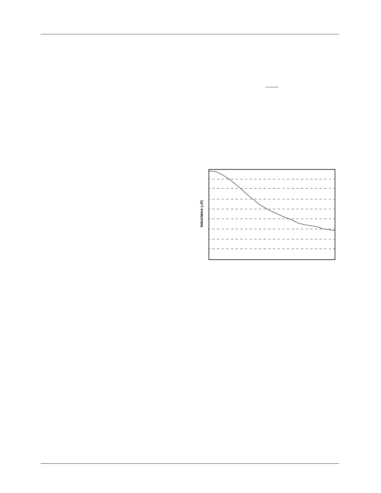
In practice, the switching power inductors used for convert-
ers always have a “soft” saturation. What this means can be
understood by viewing a plot of actually measured induc-
tance vs. DC current:
9
8
7
6
5
4
3
2
1
0
0 1 2 3 4 5 6 7 8 9 10 11 12 13 14 15 16 17 18 19 20
Current (A)
This inductor has a “soft” saturation characteristic because
its inductance doesn’t radically decrease at some particular
current: as the current increases, the inductance very gradu-
ally tails off.
NOTE: The relatively large drop in inductance shown in this
curve is typical of most inductors such as toroids, gapped E-
cores, etc. However, rod core inductors show almost no
change in inductance at almost any current.
Given this soft saturation characteristic, it is apparent that in
most converters, it is adequate to specify the inductor’s mini-
mum inductance at the DC output current; adding a little bit
of extra current due to the ripple doesn’t greatly affect the
inductance. In most applications, ripple current will be rela-
tively small anyway, since it directly impacts output ripple
voltage. Thus it is common practice in the industry to specify
inductance at the DC output current, and to ignore the ripple
current in the spec.
2
Share Link: 