ACT8798(2008) View Datasheet(PDF) - Active-Semi, Inc
Part Name
Description
Manufacturer
ACT8798
(Rev.:2008)
(Rev.:2008)
Active-Semi, Inc

ACT8798 Datasheet PDF : 34 Pages
| |||
ACT8798
Rev0, 10-Oct-08
SYSTEM MANAGEMENT
FUNCTIONAL DESCRIPTION (CONT’D)
nMSTR Enable Input
In most applications, connect nMSTR to an active
low, momentary push-button switch to utilize the
ACT8798's closed-loop enable/disable functionality.
If a momentary-on switch is not used, drive nMSTR
to GA or to a logic low to initiate a startup se-
quence.
Enable/Disable Inputs
The ACT8798 provides two manual enable/disable
inputs, PWRHLD and ON3. PWRHLD is the master
enable input. When driven high, PWRHLD enables
REG1, REG2, and REG4, and also activates the
enable/disable control logic for the other regulators.
ON3 is the enable input for REG3, and is active
when either of the following conditions exists:
1) nMSTR is asserted low, or
2) PWRHLD is asserted high.
Power-On Reset Output
The ACT8798 integrates a 260ms power-on reset
generator, reducing system size and cost. nRSTO
is an open-drain output. Connect a 10kΩ or greater
pull-up resistor from nRSTO to an appropriate volt-
age supply. nRSTO asserts low upon startup and
remains low until the reset-timeout period expires,
at which point nRSTO goes high-Z.
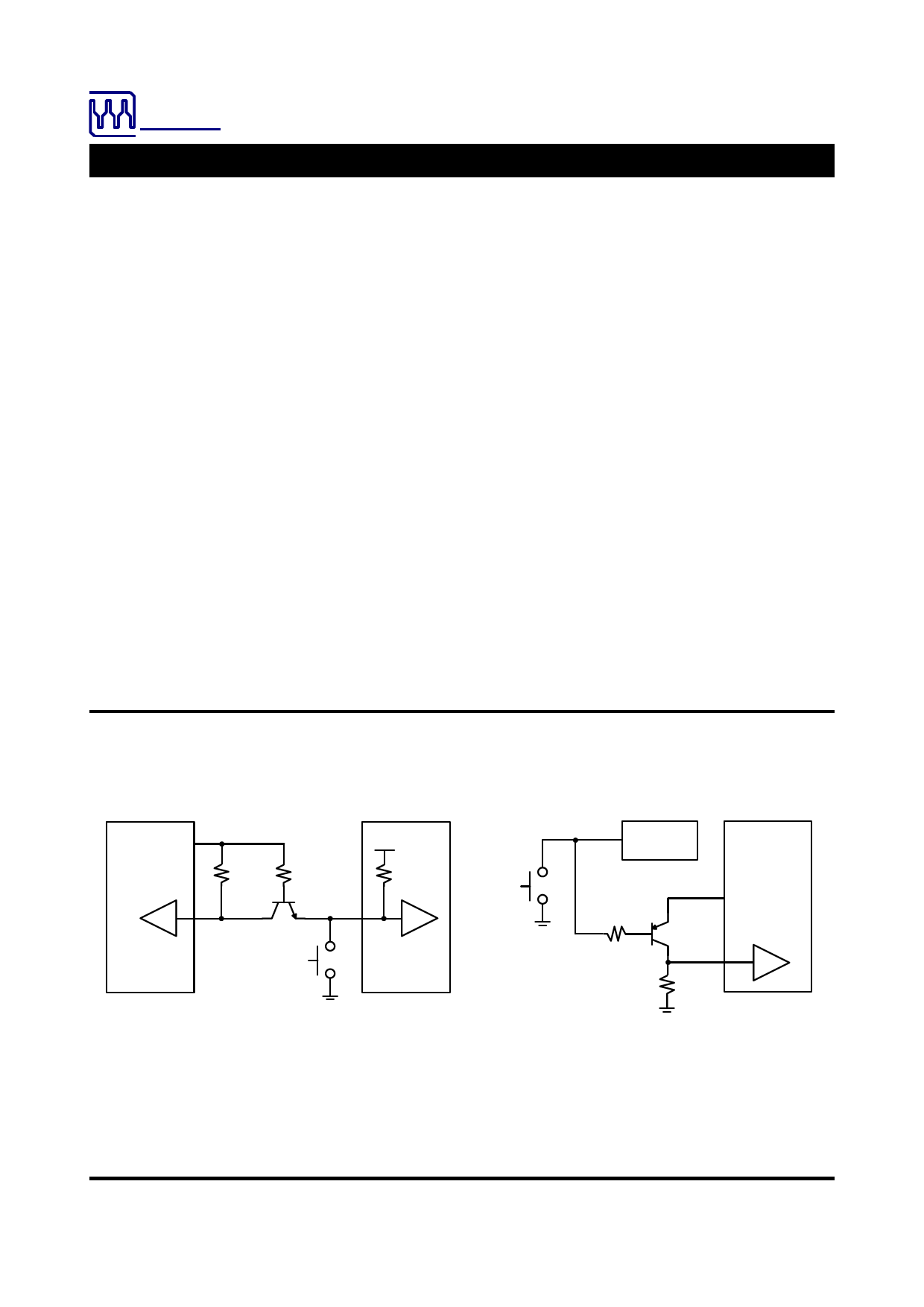
nIRQ Output
Figure 2 shows two simple circuits that can be used
to generate nIRQ, a processor interrupt signal,
which can be used as part of the ACT8798’s push-
button control logic. This signal is typically used to
drive the interrupt input of the system processor,
and is useful in a variety of software-controlled en-
able/disable control routines. Figure 2A provides an
active-low, open-collector push-button status output
that sinks current when nMSTR is driven to a logic-
low. Figure 2B provides an active-high, open-
collector push-button status output that sources
current when nMSTR is driven to a logic-low.
Thermal Shutdown
The ACT8798 integrates thermal shutdown protec-
tion circuitry to prevent damage resulting from ex-
cessive thermal stress, as may be encountered un-
der fault conditions. This circuitry disables all regu-
lators if the ACT8798 die temperature exceeds
160°C, and prevents the regulators from being en-
abled until the IC temperature drops by 20°C (typ).
Figure 2:
Simple Circuits
OUT2
VCC
INL
100k 100k
500k
nIRQ
PB
CPU
ACT8798
nMSTR
ACT8798
PB
OUT2
100k
VCC
nIRQ
100k
(A)
(B)
Innovative PowerTM
ActivePMUTM is a trademark of Active-Semi.
I2CTM is a trademark of Philips Electronics.
- 11 -
www.active-semi.com
Copyright © 2008 Active-Semi, Inc.
Share Link: