AD7150BRMZ-REEL(Rev0) View Datasheet(PDF) - Analog Devices
Part Name
Description
Manufacturer
AD7150BRMZ-REEL
(Rev.:Rev0)
(Rev.:Rev0)
Analog Devices

AD7150BRMZ-REEL Datasheet PDF : 28 Pages
| |||
COMPARATOR AND THRESHOLD MODES
The AD7150 comparators and their thresholds can be
programmed to operate in several different modes. In an
adaptive mode, the threshold is dynamically adjusted and the
comparator output indicates fast changes and ignores slow
changes in the input (sensor) capacitance. Alternatively, the
threshold can be programmed as a constant (fixed) value, and
the output then indicates any change in the input capacitance
that crosses the defined fixed threshold.
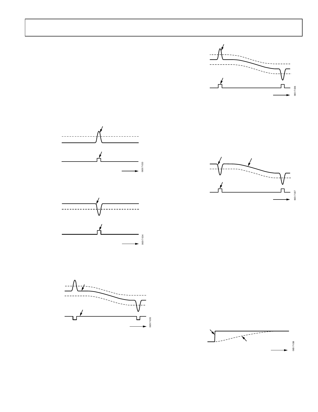
The AD7150 logic output (active high) indicates either a positive or
a negative change in the input capacitance, in both adaptive and
fixed threshold modes (see Figure 25 and Figure 26).
POSITIVE CHANGE
POSITIVE
THRESHOLD
INPUT
CAPACITANCE
OUTPUT ACTIVE
OUTPUT
TIME
Figure 25. Positive Threshold Mode
Indicates Positive Change in Input Capacitance
INPUT
CAPACITANCE
NEGATIVE
THRESHOLD
NEGATIVE CHANGE
OUTPUT ACTIVE
OUTPUT
TIME
Figure 26. Negative Threshold Mode
Indicates Negative Change in Input Capacitance
Additionally, for the adaptive mode only, the comparators can
work as window comparators, indicating input either inside or
outside a selected sensitivity band (see Figure 27 and Figure 28).
POSITIVE
THRESHOLD
INPUT CAPACITANCE
NEGATIVE
THRESHOLD
INPUT INSIDE THRESHOLD WINDOW
OUTPUT ACTIVE
OUTPUT
TIME
Figure 27. In-Window (Adaptive) Threshold Mode
AD7150
INPUT OUTSIDE THRESHOLD WINDOW
POSITIVE
THRESHOLD
INPUT CAPACITANCE
NEGATIVE
THRESHOLD
OUTPUT ACTIVE
OUTPUT
TIME
Figure 28. Out-Window (Adaptive) Threshold Mode
ADAPTIVE THRESHOLD
In an adaptive mode, the thresholds are dynamically adjusted,
ensuring indication of fast changes (for example, an object
moving close to a capacitive proximity sensor) and eliminating
slow changes in the input (sensor) capacitance, usually caused
by environment changes such as humidity or temperature or
changes in the sensor dielectric material over time (see Figure 29).
FAST CHANGE
SLOW CHANGE
INPUT CAPACITANCE
THRESHOLD
OUTPUT ACTIVE
OUTPUT
TIME
Figure 29. Adaptive Threshold
Indicates Fast Changes and Eliminates Slow Changes in Input Capacitance
DATA AVERAGE
The adaptive threshold algorithm is based on an average calculated
from previous CDC output data. The response of the average to an
input capacitance step change (more exactly, response to the change
in the CDC output data) is an exponential settling curve, which can
be characterized by the following equation:
Average(N ) = Average(0) + Change(1 − eN / TimeConst )
where:
Average(N) is the value of average N complete CDC conversion
cycles after a step change on the input.
Average(0) is the value before the step change.
TimeConst can be selected in the range between 2 and 65,536, in
steps of power of 2, by programming the ThrSettling bits in the
setup registers.
See Figure 30 and the Register Descriptions section.
INPUT CAPACITANCE
(CDC DATA) CHANGE
DATA AVERAGE RESPONSE
TIME
Figure 30. Data Average Response to Data Step Change
Rev. 0 | Page 11 of 28
Share Link: