ADP1655 View Datasheet(PDF) - Analog Devices
Part Name
Description
Manufacturer
ADP1655 Datasheet PDF : 24 Pages
| |||
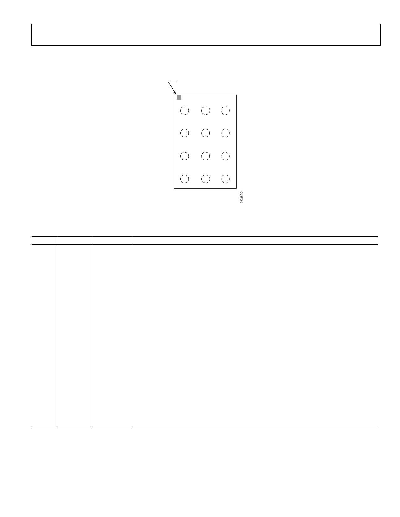
PIN CONFIGURATION AND FUNCTION DESCRIPTIONS
BALL A1
INDICATOR
1
2
3
PGND SGND
VIN
A
SW
TORCH TX_MASK
B
VOUT STROBE I2C/EN
C
LED_OUT SDA/EN2 SCL/EN1
D
TOP VIEW
(BALL SIDE DOWN)
Not to Scale
Figure 4. Pin Configuration
ADP1655
Table 5. Pin Function Descriptions
Pin No. Mnemonic Type
A1
PGND
Ground
A2
SGND
Ground
A3
VIN
Supply
B1
SW
Output
B2
TORCH
Digital Input
B3
TX_MASK Digital Input
C1
VOUT
Output
C2
STROBE
Digital Input/
Output
C3
I2C/EN
Digital Input
D1
LED_OUT Output
D2
SDA/EN2 Digital Input/
Output
D3
SCL/EN1 Digital Input
Description
Ground for Internal Switching FET.
Connect this pin at a single point to the power ground.
Connect the battery between VIN and PGND. Bypass VIN with a 10 μF, 6.3 V or greater X5R/X7R
capacitor.
Connect a 2.2 μH inductor between SW and the battery.
This pin enables the torch, provided that the device is not in flash or assist light mode.
Connect a digital signal to the TX_MASK pin. When the logic level is driven high during a flash
event the current is reduced to the torch level.
VOUT senses the output voltage of the boost converter and provides the input voltage to the LED
current source. The VOUT pin features a comparator to detect an overvoltage condition if the LED
string is open circuited. Connect a 10.0 μF capacitor between VOUT and PGND.
The STROBE input is used to synchronize the timing of the camera module to the LED driver in
I2C-compatible interface mode. In 2-bit logic interface mode, this acts as an output, indicating the
number of LEDs attached. STROBE = high indicates two LEDs, whereas STROBE = low indicates
one LED.
A logic low selects the 2-bit logic interface, whereas logic high selects I2C-compatible interface. If
I2C/EN is low and SDA/EN2 and SCL/EN1 are low, the driver enters shutdown mode with
consumption < 1 μA.
White LED Anode Connection. Connect LED_OUT to the anode of the white LED. LED_OUT is
internally connected to a programmable PMOS current source, which regulates the LED current.
Data Input/Output (SDA). In 2-bit logic interface mode, SDA/EN2 is the second input bit of the
digital interface.
Second Input Bit (EN2). In I2C mode, SDA is the data input/output of the I2C-compatible interface.
Clock Input (SCL). In 2-bit logic interface mode, SCL/EN1 is the first input bit of the digital interface.
First Input Bit (EN1). In I2C mode, SCL is the clock input of the I2C-compatible interface.
Rev. 0 | Page 7 of 24
Share Link: 