AGB3311 View Datasheet(PDF) - ANADIGICS
Part Name
Description
Manufacturer
AGB3311 Datasheet PDF : 8 Pages
| |||
AGB3311
Table 4: Electrical Specifications
(TA = +25 °C, VSUPPLY = +5 VDC, 50Ω system)
PARAMETER
MIN TYP MAX
UNIT
Gain (S21)
850 MHz -
20
-
1950 MHz -
2140 MHz -
17.5
-
17.5
-
dB
2450 MHz -
16.5
-
Output IP3 (1)
850 MHz -
+27
-
1950 MHz -
+27
-
2140 MHz -
+27
-
2450 MHz -
+27
-
dBm
Output 1dB Compression (P1dB)
850 MHz -
+15
-
dBm
Noise Figure
850 MHz -
6
-
dB
Thermal Resistance ( θJC)
-
320
-
°C/W
Supply Current (ICC)
-
37
-
mA
Notes:
(1) OIP3 is measured with two tones at 1 MHz spacing at 0 dBm output power
per tone.
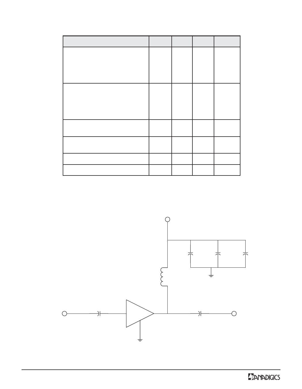
2. Performance as measured on ANADIGICS test fixture (see Figure 3).
All capacitors are muRata GRM39 series.
The inductor is a Coilcraft 0603CS series.
+5 VDC
100 nH
10 pF 100 pF 0.01 µF
RF Input
0.01 µF
AGB3311
0.01 µF
RF Output
Figure 3: Application Circuit (50 Ω Terminations)
4
PRELIMINARY DATA SHEET - Rev 1.0
07/2003
Share Link: 