AP7365-XXYG-13(2020) View Datasheet(PDF) - Diodes Incorporated.
Part Name
Description
Manufacturer
AP7365-XXYG-13
(Rev.:2020)
(Rev.:2020)
Diodes Incorporated.

AP7365-XXYG-13 Datasheet PDF : 18 Pages
| |||
AP7365
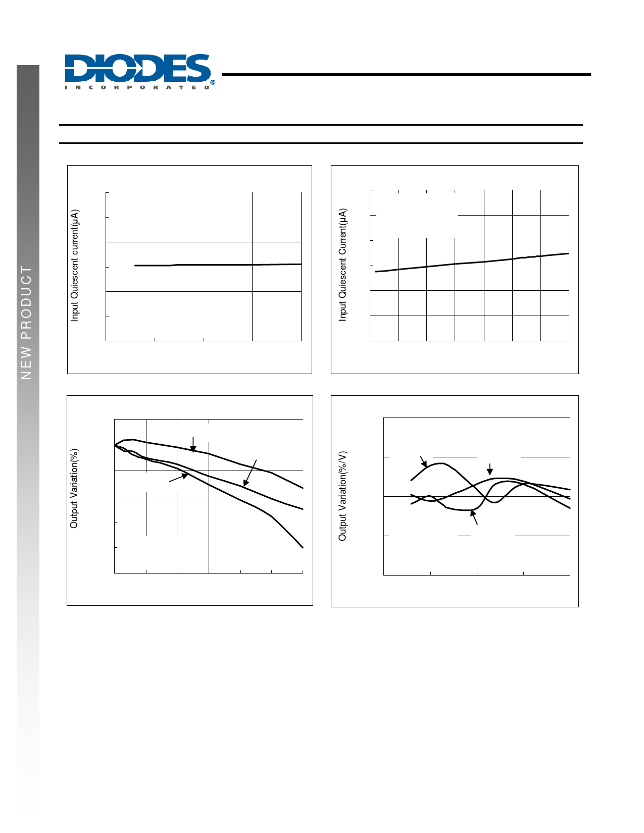
Typical Performance Characteristics (continued)
2.0
1.6
1.2
0.8
0.4
VIN = 4.3V
VOUT = 3.3V
0.0
-50 -25 0 25 50 75 100 125
TEMPERATURE ((°癈C))
Current Limit vs. Temperature
Application Information
Input Capacitor
A 1µF ceramic capacitor is recommended between IN and GND pins to decouple input power supply glitch and noise. The amount of the
capacitance may be increased without limit. This input capacitor must be located as close as possible to the device to assure input stability and
reduce noise. For PCB layout, a wide copper trace is required for both IN and GND pins. A lower ESR capacitor type allows the use of less
capacitance, while higher ESR type requires more capacitance.
Output Capacitor
The output capacitor is required to stabilize and improve the transient response of the LDO. The AP7365 is stable with very small ceramic output
capacitors. Using a ceramic capacitor value that is at least 1μF with ESR > 15mΩ on the output ensures stability. Higher capacitance values help
to improve line and load transient response. The output capacitance may be increased to keep low undershoot and overshoot. Output capacitor
must be placed as close as possible to OUT and GND pins.
100
10
1
0.1
Unstable Range
Unstable Range
Stable Range
VVININ== 44..33VV
CCININ== CCOOUUTT==1µ1F礔
0.01
USntsatbalbeleRRaannggee
0.001
0
100 200 300 400 500 600
LOAD CURRENT (mA)
Region of Stable COUT ESR vs. Load Current
AP7365
Document number: DS32260 Rev. 11 - 3
8 of 18
www.diodes.com
March 2020
© Diodes Incorporated
Share Link: