APR9301-V2-1 View Datasheet(PDF) - APLUS INTEGRATED CIRCUITS
Part Name
Description
Manufacturer
APR9301-V2-1
APLUS INTEGRATED CIRCUITS

APR9301-V2-1 Datasheet PDF : 7 Pages
| |||
APLUS
APR9301-V2
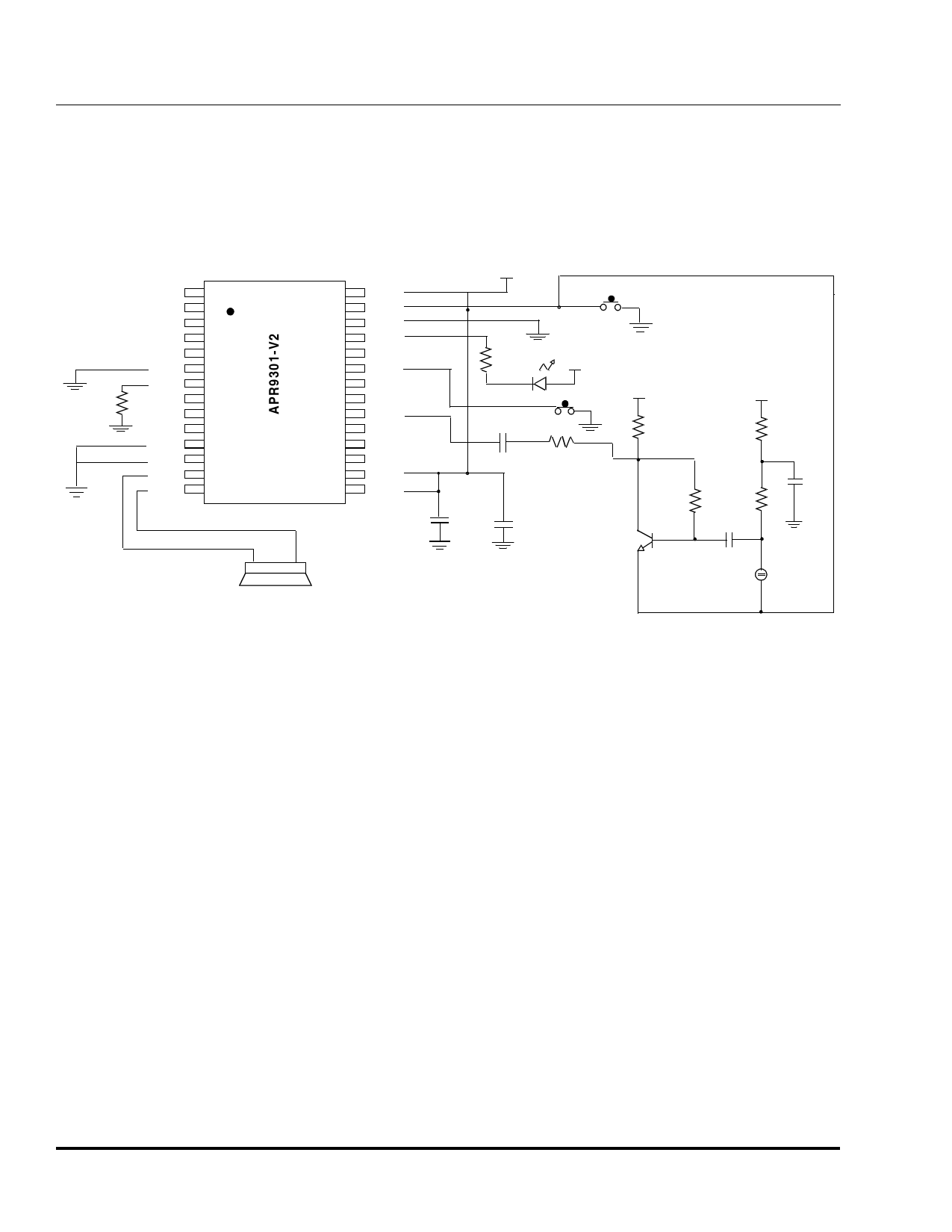
Figure 4 shows the same application using external
microphone biasing instead of the microphone amplifier on
the APR9301-V2 , thus bypassing the preamplifier portion
of the chip function.
Figure 4 Sample Application Using External Microphone Biasing
NC
1
NC
2
NC
3
NC
4
NC
5
/CE
6
OscR
7
NC
8
52K
NC
9
NC
10
NU1
11
VSS
12
SP+
13
SP-
14
28
VCCD
27
/R e cL
26
VSSD
25
/LED
24
NC
23
/P la yE
22
NC
21
NC
20
A n a In
19
NC
18
NC
17
NC
16
VccA_R
15
VccA_L
0.1 µF
VCC(6VDC)
2K
VCC
0.1µF
47µF
8 Ohm Speaker
VCC
10K
100K
T1
VCC
1K
22µF
R2
0.1uF
Electret
M icrophone
Notes:
NC = No Connect (must be floating).
Pins 23 and 27 have internal pull-up resistors.
The typical sampling frequency is 6.4 kHz with OscR = 52 kW.
NPN bipolar transistor, T1 model #MPS3904 or equivalent.
R1 and R2 are recommended to be 30 kW and 10 kW, respectively, for typical applications.
Substrate should be connected to GND.
Electrical Characteristics
Tables 2 through 4 list Absolute Maximum Ratings,
Recommended DC Characteristics, and recommended
Analog Characteristics for the APR9301-V2 device.
Absolute Maximum Ratings
Stresses greater than those listed in Table 2 may cause
permanent damage to the device. These specifications
represent a stress rating only. Operation of the device at
these or any other conditions above those specified in the
recommended DC Characteristics or recommended Analog
Characteristics of this specification is not implied. Operation
of the device at maximum conditions for extended periods
may affect reliability.
Page 4
Share Link: