AS1907 View Datasheet(PDF) - austriamicrosystems AG
Part Name
Description
Manufacturer
AS1907 Datasheet PDF : 10 Pages
| |||
AS1907/AS1908/AS1909
Datasheet - Application Information
8 Application Information
8.1 Negative Going VCC Transients
All devices are effectively immune to short-duration, negative-going VCC transients (glitches). The Maximum Transient Duration vs. Reset
Comparator Overdrive graph (see page 5) shows the maximum pulse width that a negative-going VCC transient may typically have without
issuing a reset signal. As the amplitude of the transient increases, the maximum allowable pulse width decreases.
8.2 Valid Reset Output
If VCC falls below 1V and approaches the minimum operating voltage of 0.7V, push/pull-type reset sinking/sourcing capabilities greatly decrease.
High-impedance CMOS-logic inputs connected to RESET can drift to indeterminate voltages, although this is normally not a problem since most
microprocessors do not operate at VCC < 1V.
For the AS1908, where RESET must be valid to VCC = 0, a 100kΩ pull-up resistor between RESET and VCC (see Figure 1 on page 1) will hold
RESET high if VCC falls below 0.7V.
For the AS1907, where RESET must be valid down to 0V, add a pull-down resistor between RESET and GND (see Figure 1 on page 1) to
eliminate stray leakage currents and hold RESET low. A pull-down resistor of 100kΩ is large enough not to load RESET yet small enough to pull
it low.
Since the AS1909 has an open-drain, active-low output, it typically uses a pull-up resistor. With this device, RESET will most likely not maintain
an active condition, but will drift to a non-active level due to the pull-up resistor and the reduced sinking capability of the open drain device.
Therefore, this device is not recommended for applications where the RESET pin is required to be valid down to VCC = 0.
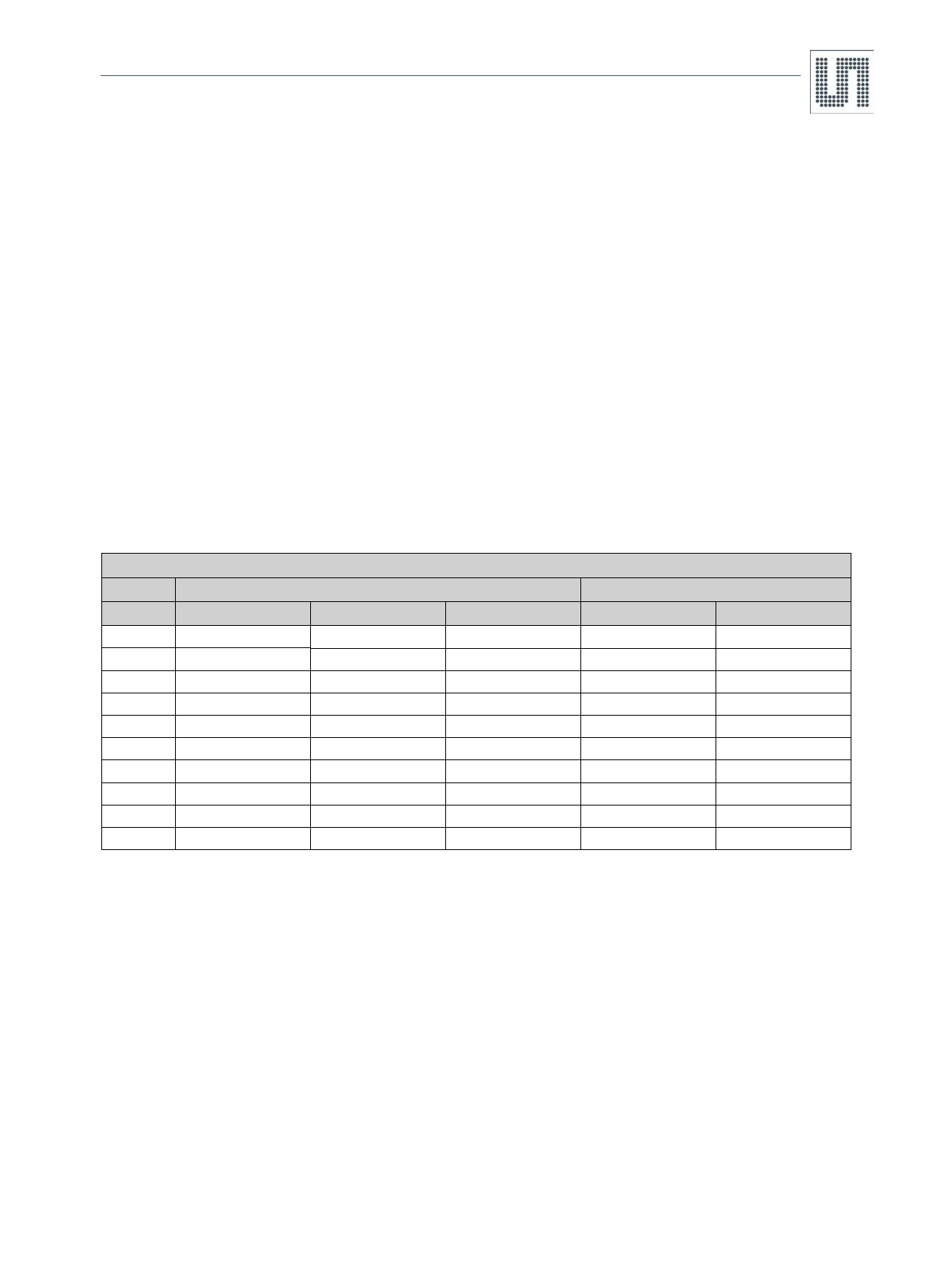
Table 5. Reset Thresholds
Reset Thresholds
TAMB = +25ºC
TAMB = -40 to +125ºC
Suffix
Min
Typ
Max
Min
Max
25
2.478
2.50
2.523
2.43
2.58
24
2.378
2.40
2.422
2.33
2.47
23
2.279
2.30
2.321
2.23
2.37
22
2.180
2.20
2.220
2.13
2.27
21
2.081
2.10
2.119
2.04
2.18
20
1.982
2.00
2.018
1.94
2.06
19
1.883
1.90
1.917
1.84
1.96
18
1.784
1.80
1.816
1.75
1.85
17
1.685
1.70
1.715
1.65
1.75
16
1.586
1.60
1.614
1.55
1.65
8.3 Bi-Directional Microprocessor Interface
The RESET output on the AS1909 is open-drain, thus this device can interface easily with microprocessors that have bi-directional reset pins,
such as the Motorola 68HC11.
Connect the RESET output of this device directly to the microprocessor’s RESET I/O pin with a single pull-up resistor to allow either device to
assert reset (see Figure 1 on page 1).
8.4 Layout Considerations
The devices require proper layout and design procedures for optimum performance.
Short, wide traces should be used to reduce stray inductance and capacitance.
Bypass capacitors should be as close to the device as possible.
Large ground planes should be used wherever possible.
www.ams.com/Supervisors/AS1907-09
Revision 1.8
7 - 10
Share Link: 