AU1564A View Datasheet(PDF) - APLUS INTEGRATED CIRCUITS
Part Name
Description
Manufacturer
AU1564A Datasheet PDF : 12 Pages
| |||
AU Series
LCD Common Plate Usage:
COM1
COM2
COM3
Alternating
frequency
Static
Yes
No
No
32Hz
1/2 duty
Yes
Yes
No
32Hz
1/3 duty
Yes
Yes
Yes
43Hz
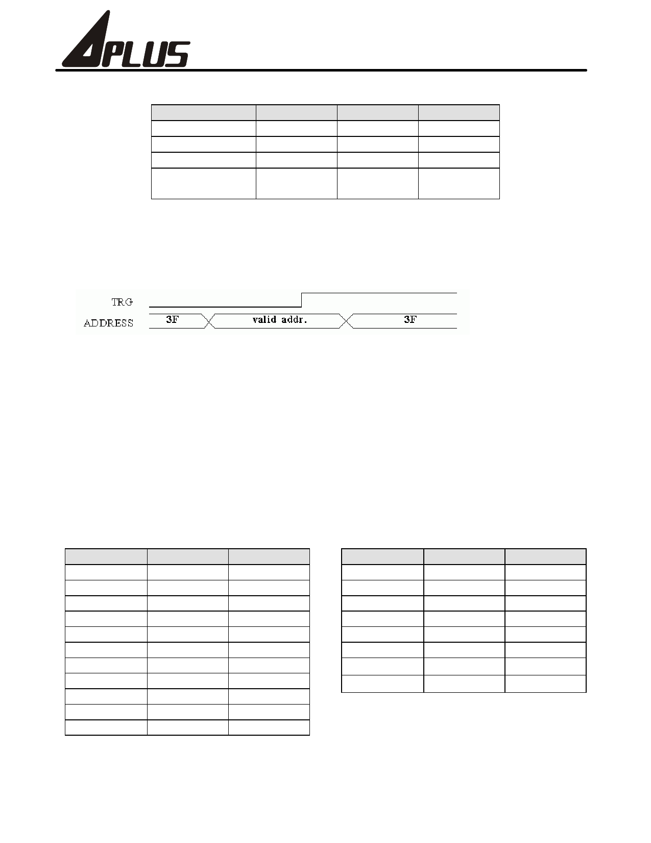
Voice Trigger:
The voice circuitry will be Triggered in the rising edge of TRG signal. The Voice section address must be placed on I/OA
and I/OB port.
I/OB2 I/OB1 I/OA4 I/OA3 I/OA2 I/OA1
(MSB)
(LSB)
a)In power on state, TRG signal is reset to "LOW" level. TRG will stay at low level until the program set it to "HIGH" level.
b) Before triggering the voice circuitry, used the OIOA and OIOB instruction to place the voice section address on I/OA and
I/OB port. The voice section address couldn't be changed until the rising edge of TRG signal.
c) After triggering voice, I/OA and I/OB ports must output 3F data or set to input mode. If not, there will be a standby
current problem.
d) Example of playing voice subroutine:
Triggering the 26th(1Ah) section
LDS 3,1
LDS 4,A
OIOB 3 ; place voice section address to i/o port
OIOA 4
RF 4 ; trigger voice
SF 4
LDS 3,3
LDS 4,F
OIOA 4 ; output 3F data to I/O port
OIOB 3
Absolute Maximum Rating: (VDD=3V, VSS2=0V)
Symbol
Rating
Unit
Symbol
Rating
Unit
VSS1
1.2-1.8
V
RESET VSS2-VDD
V
GND
0-0.6
V
TRG
VSS2-VDD
V
CUP1 VSS2-VSS1
V
P1-P4 VSS2-VDD
V
CUP2
VSS1-VDD
V
SEG1-24 VSS2-VDD
V
OSCIN GND-VDD
V
COM1-3 VSS2-VDD
V
OSCOUT GND-VDD
V
VOUT1-2 VSS2-VDD
V
S1-S4 VSS2-VDD
V
T(operating) -10-+60
℃
M1-M4 VSS2-VDD
V
T(storage) -55-+125
℃
IOA1-IOA4 VSS2-VDD
V
IOB1-IOB4 VSS2-VDD
V
INT/BUSY VSS2-VDD
V
3
Rev 2.0
Share Link: 