BR9016F View Datasheet(PDF) - ROHM Semiconductor
Part Name
Description
Manufacturer
BR9016F Datasheet PDF : 11 Pages
| |||
Memory ICs
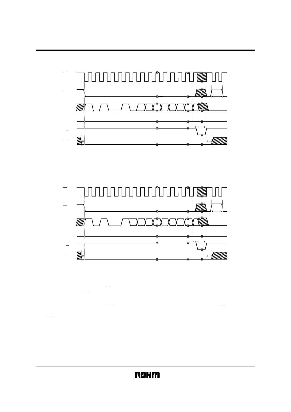
(4) Write cycle
BR9080 / F / RFV
H
SK
L
H
CS
L
H
DI
L
DO
H
R/B
WC
BR9080 / BR9080F / BR9080RFV /
BR9016 / BR9016F / BR9016RFV
1
4
8
16
32
1 01
00 1
0 A0 A1
HIGH-Z
tCS
A7 A8 D0
D15
HIGH-Z
tSV
tE-W
tWCS
tWCH
Fig.6 BR9080 / F / RFV
BR9016 / F / RFV
H
SK
L
H
CS
L
H
DI
L
DO
H
R/B
WC
1
4
8
1 01
0 0 1 A0 A1 A2
HIGH-Z
tWCS
16
32
tCS
A8 A9 D0
D15
HIGH-Z
tSV
tE-W
tWCH
Fig.7 BR9016 / F / RFV
1) At the rising edge of 32nd clock, R / B pin will be come out “LOW” after the specified time delay (tSV).
2) From above edge R / B will indicate the ready / busy status of the chip: “LOW” indicated programming is all in
progress: “HIGH” indicates the write cycle is complete and this part is ready for another instruction.
3) During the input of Write command, CS must be “LOW”. However, once the write operation started, CS could be either
“HIGH” or “LOW”.
4) If WC becomes “HIGH” during Write Cycle, the write operation is halted. In this case, the address data in writing is no
guaranteed. It is necessary to rewrite it.
Share Link: 