ZXCP330 View Datasheet(PDF) - Zetex => Diodes
Part Name
Description
Manufacturer
ZXCP330 Datasheet PDF : 9 Pages
| |||
ZXCP330
Capacitor selection
Layout considerations
An absolute minimum value of 220nF for the flying
capacitor is needed to obtain maximum output current
and 330nF is probably safer with tolerance in mind.
However much lower capacitors can be used if the
device is being used at light loads. An output capacitor
of 10F is recommended and this should be as low an
ESR as possible as the output consists of large current
spikes, so ceramics are preferred. Because the flying
capacitor charges from the input via a switch, inrush
current is also large and a low ESR capacitor should be
used for input decoupling.
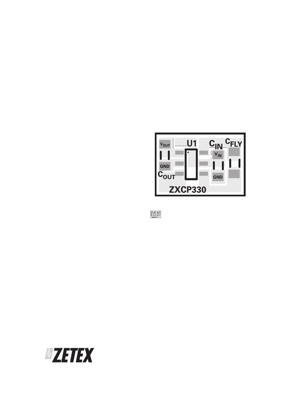
Careful layout of the ZXCP330 application circuit is
essential for correct operation because of its high
switching frequency and transient currents. For
optimum converter performance use a ground plane
and keep PCB tracks to all capacitors short to minimise
output voltage ripple and maintain regulation under all
conditions.
The recommended layout configuration is shown
below:
The device senses the output voltage in order to
regulate at 3.3V and any inductance in series with
either end of the output capacitor will cause ringing
which will not be damped as the output capacitor has
low ESR. This is very undesirable from a regulation or
ripple aspect, therefore short connections must be
used between device pins and all capacitors (see
Layout Considerations later) to keep the waveforms as
clean as possible.
The dielectric of the ceramic capacitor is an important
consideration for the ZXCP330 operation over
temperature. Zetex recommends minimum dielectric
specification of X7R for the flying capacitor and X5R for
the input and output capacitors. Capacitors used with a
lower specification dielectric can cause excessive
noise and output voltage ripple and can also
compromise output current over temperature. For
example a ceramic capacitor with an X7R dielectric will
lose 20% of its capacitance over a -40ЊC to 85ЊC
temperature range, whereas a capacitor with a Y5V
dielectric loses 80% of its capacitance at -40ЊC and 75%
at 85ЊC.
Image enlarged to show detail.
Actual size (8mmx5.3mm)
Thermal management
At high input voltages and load currents the ZXCP330
power dissipation is high. As mentioned previously,
the ZXCP330 will shutdown when the junction
temperature of the device reaches 150ЊC. To reduce the
junction temperature of the device a good thermal
connection to the PCB is necessary. This can be
achieved by connecting the GND pin of the ZXCP330 to
a solid ground plane running on the second layer of a 2
layer PCB, adding extra heatsinking.
PROVISIONAL ISSUE A - DECEMBER 2001
6
Share Link: 