BT856 View Datasheet(PDF) - Unspecified
Part Name
Description
Manufacturer
BT856 Datasheet PDF : 54 Pages
| |||
Bt856/7
CIRCUIT DESCRIPTION
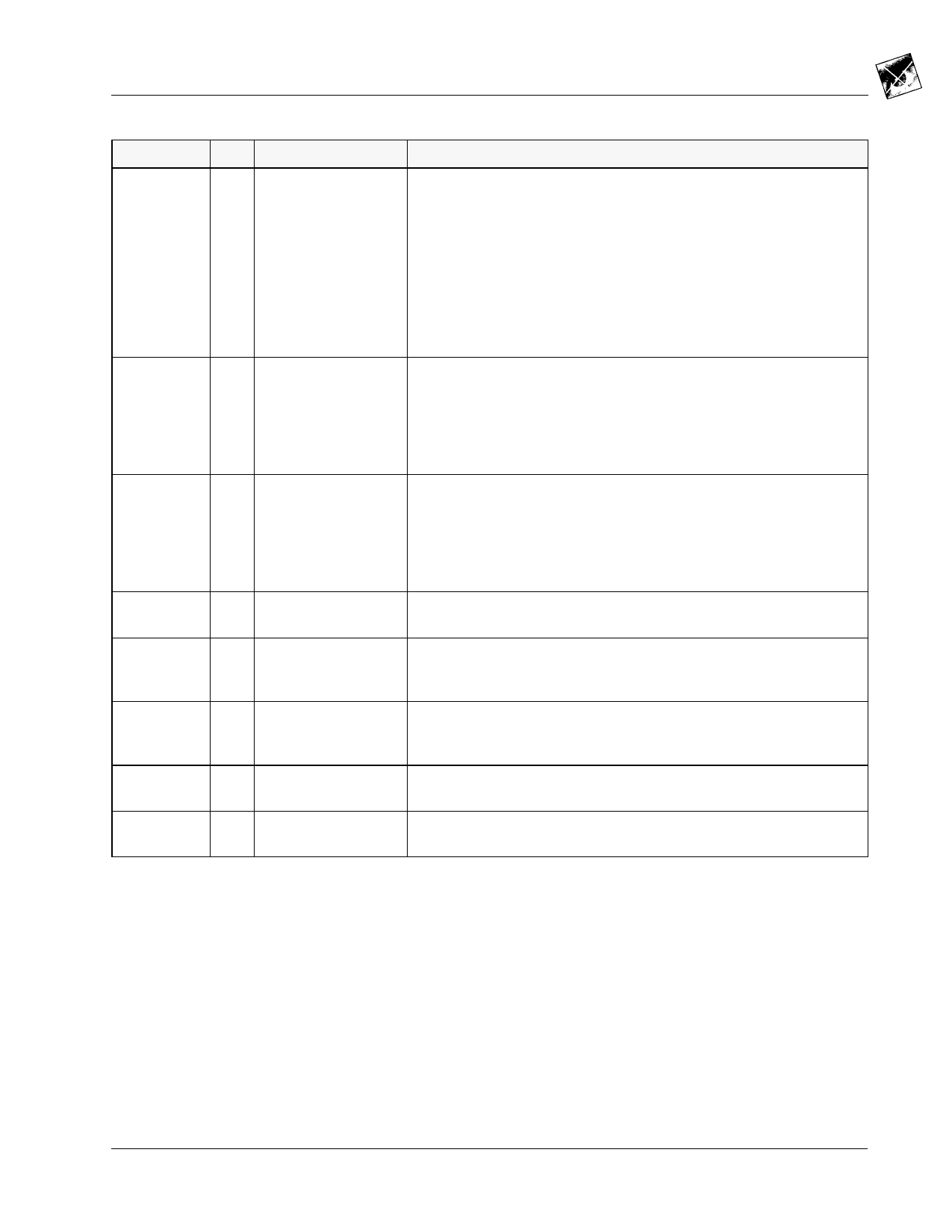
Pin Descriptions
Pin Name
PAL
I/O
I 60
Pin #
FS ADJUST
62
VREF_IN
I 63
VREF_OUT O 64
COMP
67
R0–R7,
G0–G7,
B0–B7
VAA
GND
I 13,14, 17–20, 23,24
36–43,
28–35
– 16,22, 51,57,
61,65, 66
– 15,21,50,56
68 1,3,5,7,9
Description
NTSC/PAL mode select input (TTL compatible). A logical one config-
ures the device for PAL (B, D, G, H, I, N) operation. A logical zero con-
figures the device for NTSC operation. This pin should be connected
directly to GND if using I2C. For non-I2C use, a 10 kΩ pullup resistor (to
VAA) MUST be used to program the Bt856/7 for PAL operation. Since
this pin is also used as an analog test pin, it cannot be connected
directly to VAA or VDD.
This pin is ignored if bit D4 of subaddress register 0xDC is a logical
one. To enable PAL–M or PAL–N (Argentina), bits D1 and D0 of register
0xDA and D5 of register 0xDC (for PAL-M setup) must be set.
Full-scale adjust control pin. A resistor (RSET) connected between this
pin and GND controls the full-scale output current on the analog out-
puts. For standard operation, use the nominal RSET values shown
under Recommended Operating Conditions. The relationship between
RSET and the full-scale output current on the DAC outputs is:
RSET (Ω) = 2,055 * VREF_IN (V) / Iout FS (mA)
Voltage reference input. VREF_IN may be connected directly to
VREF_OUT. An external voltage reference can supply this input with a
1.235 V (typical) reference. A 0.1 µF ceramic capacitor must be used to
decouple this input to GND, as shown in Figures 15 and 16 in the PC
Board Layout section. The decoupling capacitor must be as close to the
device as possible to keep lead lengths to an absolute minimum.
Voltage reference output. This pin should only be used to drive the
VREF_IN pin. See Figure 16.
Compensation pin. A 0.1 µF ceramic capacitor must be used to bypass
this pin to VAA. The capacitor must be as close to the device as possi-
ble to keep lead lengths to an absolute minimum.
RGB or YCrCb (G7:B0) pixel inputs (TTL compatible). A higher index
corresponds to a greater significance.
Analog power. All VAA pins must be connected together on the same
PCB plane to prevent latchup.
Analog ground. All GND pins must be connected together on the same
PCB plane to prevent latchup.
Brooktree®
3
Share Link: 