BU1424K View Datasheet(PDF) - ROHM Semiconductor
Part Name
Description
Manufacturer
BU1424K Datasheet PDF : 30 Pages
| |||
Multimedia ICs
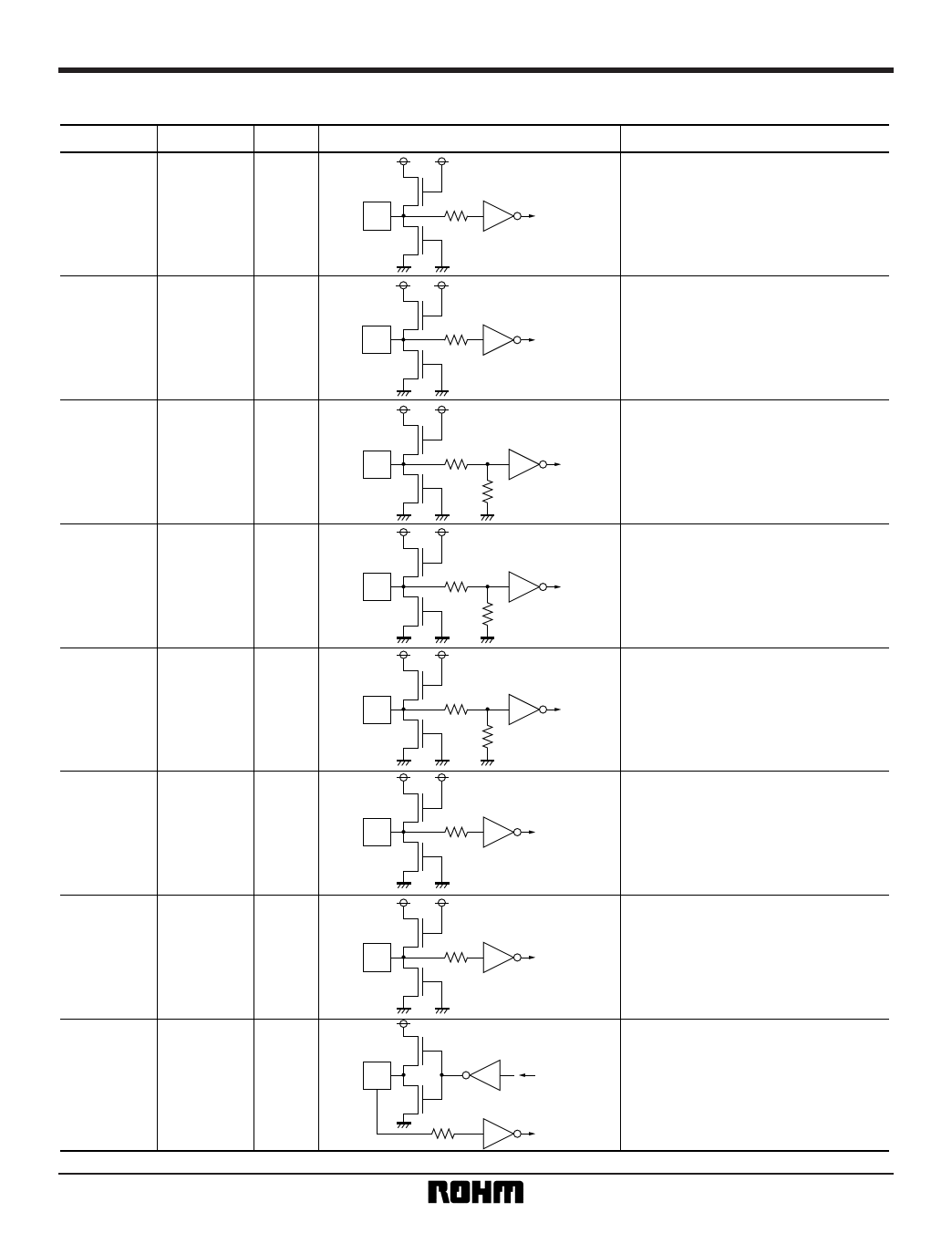
•Equivalent circuits
Pin No.
Pin name I / O
2~8
GD (7: 0)
I
10
11 ~ 14
BD (7: 0)
I
17 ~ 20
54 ~ 56
58 ~ 60
RD (7: 0)
I
62.63
1
ROSD
57
64
GOSD
BOSD
I
15
OSDSW
23
24
IM0
IM1
I
16
CDGSWB
I
22
NTB
I
28
HSY
I/O
Equivalent circuit
BU1424K
Function
G data input pin for 24-bit RGB input.
Y data input pin for 16-bit YUV input.
B data input pin for 24-bit RGB input.
U, V data input pins for 16-bit YUV
input.
R data input pin for 24-bit RGB input.
OSD data input pin when using the
OSD function.
When the OSDSW pin is HIGH, input
to the ROSD, GOSD, and BOSD pins
takes precedence over RGB, and the
data is converted.
Control pins used to select RGB (24-
bit), YUV (16-bit) or DAC Through as
the input mode.
Switches the mode between Video-
CD (HIGH) and CD-G (LOW).
Switches the mode between NTSC
(LOW) and PAL (HIGH).
This is the horizontal synchronization
signal pin. Negative polarity HSYNC
signals are input (when SLABEB =
LOW) or output (when SLABEB =
HIGH) here. This is also used as the
synchronization signal for fixing the
PIXCLK output phase.
7
Share Link: 