S80C851-4N44 View Datasheet(PDF) - Philips Electronics
Part Name
Description
Manufacturer
S80C851-4N44 Datasheet PDF : 22 Pages
| |||
Philips Semiconductors
CMOS single-chip 8-bit microcontroller
with on-chip EEPROM
Product specification
80C851/83C851
1998 Jul 03
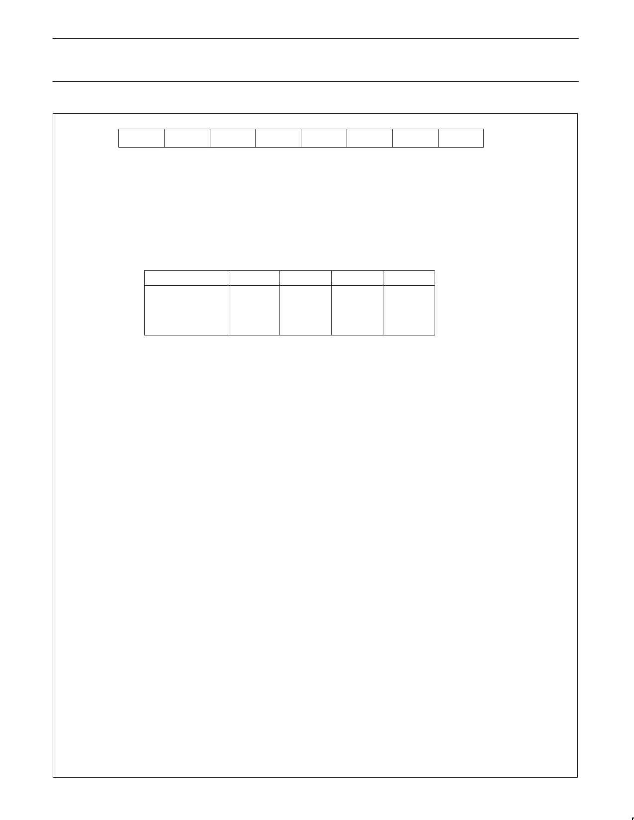
7
6
5
IFE
EEINT
EWP
4
3
2
1
0
––
ECNTRL3 ECNTRL2 ECNTRL1 ECNTRL0
Bit
Symbol
ECNTRL.7 IFE
ECNTRL.6 EEINT
ECNTRL.5 EWP
ECNTRL.4
ECCTRL.3–
ECNTRL.0
Function
Active high EEPROM interrupt flag: set by the sequencer or by software;
reset by software.
When set and enabled, this flag forces an interrupt to the same vector as the
serial port interrupt (see Interrupt section).
EEPROM interrupt enable: set and reset by software (active high).
Erase/write in progress flag: set and reset by the sequencer (active high).
When EWP is set, access to the EEPROM is not possible. EWP cannot be set or
reset by software.
Reserved.
See table below.
Operation
Byte mode
Row erase
Page write*
Page erase/write*
block erase
*Future products.
ECNTRL.3
0
1
–
–
1
ECNTRL.2
0
1
–
–
0
ECNTRL.1
0
0
–
–
1
ECNTRL.0
0
0
–
–
0
Byte mode:
Read mode:
Write mode:
Row erase:
Page write:
Page erase/write:
Block erase:
Normal EEPROM mode, default mode after reset. In this mode, data can be read and
written to one byte at a time.
This is the default mode when byte mode is selected. This means that the contents of the
addressed byte are available in the data register.
This mode is activated by writing to the data register. The address register must be loaded
first. Since the old contents are read first (by default), this allows the sequencer to decide
whether an erase/write or write cycle only (data = 00H) is required.
In this mode, the addressed row is cleared. The three LSBs of EADRL are not significant,
i.e. the 8 bytes addressed by EADRL are cleared in the same time normally needed to clear
one byte (tROWERASE = tE = tW). For the following write modes, only the write and not the
erase/write cycle is required. For example, using the row erase mode, programming 8 bytes
takes tTOTOAL = tE + 8 × tW compared to tTOTAL = 8 × tE + 8 × tW (tE = tERASE ⋅ tW = tWRITE).
For future products.
For future products.
In this mode all 256 bytes are cleared. The byte containing the security bits is also cleared.
tBLOCKERASE = tE. The contents of EADRH, EADRL and EDAT are insignificant.
Program Sequences and Register Contents after Reset
The contents of the EEPROM registers after a Reset are the default values:
EADRH = 1xxxxxxxB (security bit address)
EADRL
= 00H
(security bit address)
ETIM
= 08H
(minimum erase time with the lowest permissible oscillator frequency)
ECNTRL = 00H
(Byte mode, read)
EDAT
= xxH
(security bit)
Initialize:
MOV ETIM, ..
MOV EADRH, ..
Read:
MOV EADRL, ..
MOV .., EDAT
Write:
MOV EADRL, ..
MOV EDAT, ..
Erase row: MOV EADRL, ..
Row address. 3LSBs don’t care
MOV ECNTRL, #0CH
Erase row mode
MOV EDAT, .. (EDAT) don’t care
Erase block: MOV ECNTRL, 0AH
Erase block mode
MOV EDAT, .. (EDAT) don’t care
If the security bit is to be altered, the program generally starts as follows:
MOV EADRH, #80H
MOV EADRL, #00H
Figure 2. Control Register (ECNTRL)
8
Share Link: 