DLD1 View Datasheet(PDF) - ITT Cannon
Part Name
Description
Manufacturer
DLD1 Datasheet PDF : 76 Pages
| |||
ZIF Connectors
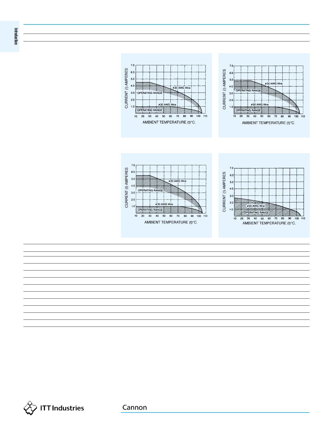
DL/DLM/DLD Temperature/Current Rating
The ambient temperature curves shown represent
the rated current carrying capacity of the Cannon
DL1/2/3/4, DLM1/2/3 and DLD1/2 electrical
connectors, derated to 80% of the values recorded
using the methods specified by International
Electro-Technical Commission Document 48
(1975).
Current was applied to the total connector (all
contacts) in one-half ampere increments and
maintained at each current level until thermal
stability was achieved. A thermocouple inserted
into the ‘‘hottest area’’ of each connector then
measured the connector temperature at the same
time that an ambient temperature reading was
taken. The difference between the two measured
values is the heat rise or self-heating created solely
by the current flow, and this temperature rise for
the current level was deducted from the insulator
material rated temperature. These values were
then derated to 80% to obtain the curves shown.
DL1/DLM1/DLD1
DL3/DLM3
DL/DLM/DLD
DL2/DLM2/DLD2
DL4
DL/DLM/DLD Test Data
Test Description
Dielectric Withstanding Voltage
Contact Resistance
Insulation Resistance
Humidity (Standard)
Humidity (DL4)
Salt Spray
Shock
Vibration (Standard)
Vibration (DL4)
MIL Standard
MIL-STD-202
MIL-STD-202
MIL-STD-202
MIL-STD-202
MIL-STD-202
MIL-STD-202
MIL-STD-202
MIL-STD-202
MIL-STD 167-1/2 Modified
Test Method
301
307
302, Condition B
103, Condition B
106
101, Condition B (48 Hours)
213, Condition A (50 G’s)
204, Condition C
—
Dimensions are shown in mm (inch)
10
Dimensions subject to change
Share Link: 