DS1305N View Datasheet(PDF) - Maxim Integrated
Part Name
Description
Manufacturer
DS1305N Datasheet PDF : 22 Pages
| |||
DS1305
3-WIRE INTERFACE
The 3-wire interface mode operates similarly to the SPI mode. However, in 3-wire mode there is one I/O
instead of separate data in and data out signals. The 3-wire interface consists of the I/O (SDI and SDO
pins tied together), CE, and SCLK pins. In 3-wire mode, each byte is shifted in LSB first unlike SPI mode
where each byte is shifted in MSB first.
As is the case with the SPI mode, an address byte is written to the device followed by a single data byte
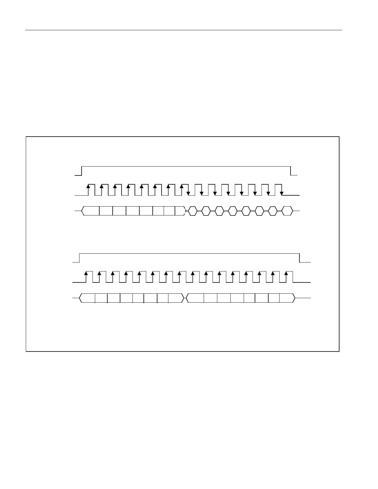
or multiple data bytes. Figure 9 illustrates a read and write cycle. In 3-wire mode, data is input on the
rising edge of SCLK and output on the falling edge of SCLK.
Figure 9. 3-WIRE SINGLE-BYTE TRANSFER
CE
SCLK
I/O*
SINGLE-BYTE READ
A0 A1 A2 A3 A4 A5 A6 0 D0 D1 D2 D3 D4 D5 D6 D7
CE
SCLK
I/O*
SINGLE-BYTE WRITE
A0 A1 A2 A3 A4 A5 A6 1
D0 D1 D2 D3 D4 D5 D6 D7
NOTE: IN BURST MODE, CE IS KEPT HIGH AND ADDITIONAL SCLK CYCLES ARE SENT UNTIL THE END OF THE BURST.
*I/O IS SDI AND SDO TIED TOGETHER.
SERMODE = GND
14 of 22
Share Link: 