DSP56300 View Datasheet(PDF) - Freescale Semiconductor
Part Name
Description
Manufacturer
DSP56300 Datasheet PDF : 108 Pages
| |||
Signals/Connections
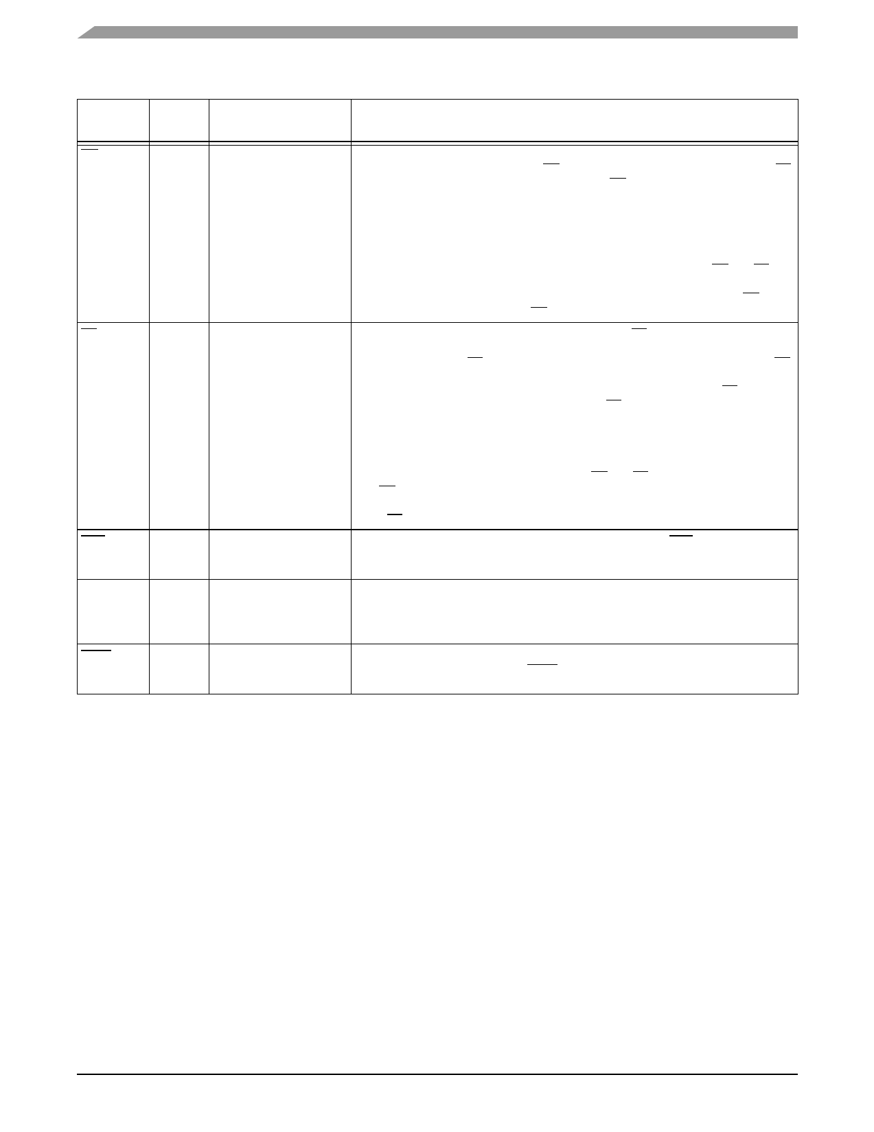
Table 1-8. External Bus Control Signals (Continued)
Signal
Name
BG
Type
Input
State During Reset,
Stop, or Wait
Signal Description
Ignored Input
Bus Grant—Asserted by an external bus arbitration circuit when the DSP56309
becomes the next bus master. When BG is asserted, the DSP56309 must wait until BB
is deasserted before taking bus mastership. When BG is deasserted, bus mastership is
typically given up at the end of the current bus cycle. This may occur in the middle of an
instruction that requires more than one external bus cycle for execution.
BB
Input/
Ignored Input
Output
The default operation of this bit requires a setup and hold time as specified in Table 2-
14. An alternate mode can be invoked: set the asynchronous bus arbitration enable
(ABE) bit (Bit 13) in the Operating Mode Register. When this bit is set, BG and BB are
synchronized internally. This eliminates the respective setup and hold time
requirements but adds a required delay between the deassertion of an initial BG input
and the assertion of a subsequent BG input.
Bus Busy—Indicates that the bus is active. Only after BB is deasserted can the
pending bus master become the bus master (and then assert the signal again). The
bus master may keep BB asserted after ceasing bus activity regardless of whether BR
is asserted or deasserted. Called “bus parking,” this allows the current bus master to
reuse the bus without rearbitration until another device requires the bus. BB is
deasserted by an “active pull-up” method (that is, BB is driven high and then released
and held high by an external pull-up resistor).
The default operation of this signal requires a setup and hold time as specified in Table
2-14. An alternative mode can be invoked by setting the ABE bit (Bit 13) in the
Operating Mode Register. When this bit is set, BG and BB are synchronized internally.
See BG for additional information.
CAS
Output Tri-stated
BCLK
Output Tri-stated
BCLK
Output Tri-stated
Note: BB requires an external pull-up resistor.
Column Address Strobe—When the DSP is the bus master, CAS is an active-low
output used by DRAM to strobe the column address. Otherwise, if the Bus Mastership
Enable (BME) bit in the DRAM control register is cleared, the signal is tri-stated.
Bus Clock
When the DSP is the bus master, BCLK is active when the Operating Mode Register
Address Trace Enable bit is set. When BCLK is active and synchronized to CLKOUT by
the internal PLL, BCLK precedes CLKOUT by one-fourth of a clock cycle.
Bus Clock Not
When the DSP is the bus master, BCLK is the inverse of the BCLK signal. Otherwise,
the signal is tri-stated.
DSP56309 Technical Data, Rev. 7
1-6
Freescale Semiconductor
Share Link: 