DSP56300FM View Datasheet(PDF) - Freescale Semiconductor
Part Name
Description
Manufacturer
DSP56300FM Datasheet PDF : 148 Pages
| |||
Interrupt and Mode Control
2.6 Interrupt and Mode Control
The interrupt and mode control signals select the chip’s operating mode as it comes out of hardware reset.
After RESET is deasserted, these inputs are hardware interrupt request lines.
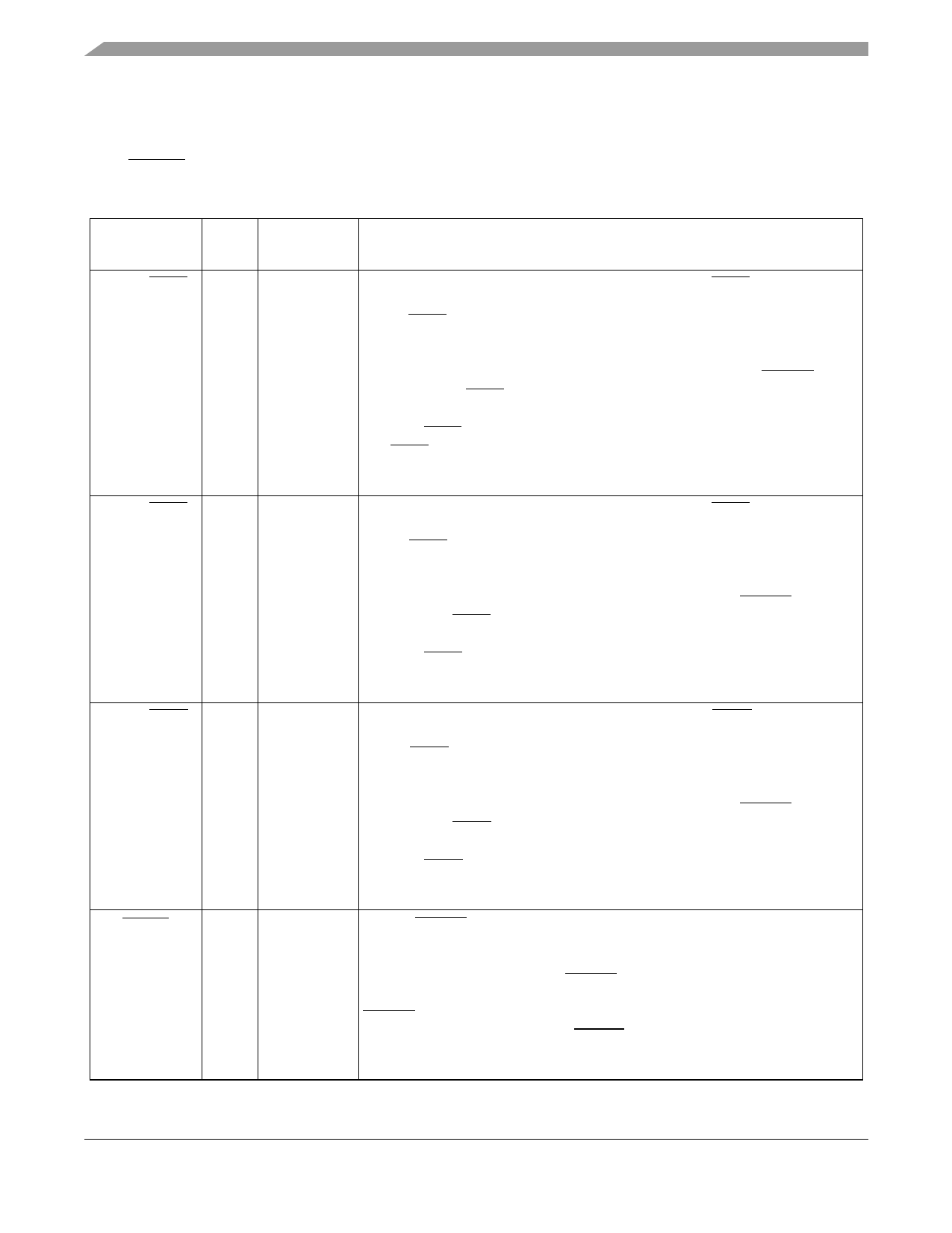
Table 2-8 Interrupt and Mode Control
Signal Name
Type
State During
Reset
Signal Description
MODA/IRQA Input
Input
Mode Select A/External Interrupt Request A—MODA/IRQA is an active-low
Schmitt-trigger input, internally synchronized to the internal system clock.
MODA/IRQA selects the initial chip operating mode during hardware reset and
becomes a level-sensitive or negative-edge-triggered, maskable interrupt request
input during normal instruction processing. MODA, MODB, and MODD select one
of 8 initial chip operating modes, latched into the OMR when the RESET signal
is deasserted. If IRQA is asserted synchronous to the internal system clock,
multiple processors can be re synchronized using the WAIT instruction and
asserting IRQA to exit the wait state. If the processor is in the stop standby state
and IRQA is asserted, the processor will exit the stop state.
This input is 5 V tolerant.
MODB/IRQB Input
Input
Mode Select B/External Interrupt Request B—MODB/IRQB is an active-low
Schmitt-trigger input, internally synchronized to the internal system clock.
MODB/IRQB selects the initial chip operating mode during hardware reset and
becomes a level-sensitive or negative-edge-triggered, maskable interrupt request
input during normal instruction processing. MODA, MODB, and MODD select one
of 8 initial chip operating modes, latched into OMR when the RESET signal is
deasserted. If IRQB is asserted synchronous to the internal system clock,
multiple processors can be re-synchronized using the WAIT instruction and
asserting IRQB to exit the wait state.
This input is 5 V tolerant.
MODD/IRQD Input
Input
Mode Select D/External Interrupt Request D—MODD/IRQD is an active-low
Schmitt-trigger input, internally synchronized to the internal system clock.
MODD/IRQD selects the initial chip operating mode during hardware reset and
becomes a level-sensitive or negative-edge-triggered, maskable interrupt request
input during normal instruction processing. MODA, MODB, and MODD select one
of 8 initial chip operating modes, latched into OMR when the RESET signal is
deasserted. If IRQD is asserted synchronous to the internal system clock,
multiple processors can be re synchronized using the WAIT instruction and
asserting IRQD to exit the wait state.
This input is 5 V tolerant.
RESET
Input
Input
Reset—RESET is an active-low, Schmitt-trigger input. When asserted, the chip
is placed in the reset state and the internal phase generator is reset. The
Schmitt-trigger input allows a slowly rising input (such as a capacitor charging) to
reset the chip reliably. When the RESET signal is deasserted, the initial chip
operating mode is latched from the MODA, MODB, and MODD inputs. The
RESET signal must be asserted during power up. A stable EXTAL signal must
be supplied before deassertion of RESET.
This input is 5 V tolerant.
DSP56364 Technical Data, Rev. 4.1
2-6
Freescale Semiconductor
Share Link: 