DTL-DB10-6 View Datasheet(PDF) - Murata Manufacturing
Part Name
Description
Manufacturer
DTL-DB10-6 Datasheet PDF : 14 Pages
| |||
DTL-IFB-485
Interface Board for Serial-Input Electronic Loads
Command Syntax (Con'td)
When operating from terminal emulation software, you can
type in BACKSPACE to edit out any unwanted or erroneous
characters before pressing ENTER.
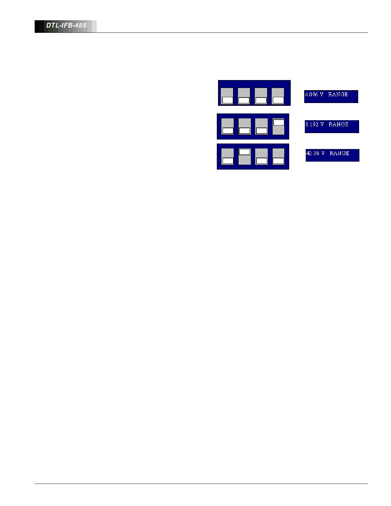
First select the desired range on the A/D channel dipswitch as
shown below:
There is a typically a delay of a few tens of milliseconds after
issuing a command and receiving the response. When
operating from a program, allowance should be made for the
fact that responses are not instantaneous.
Typical Program Sequences
In typical burn in or test set up configurations, there will be
multiple loads and units under test connected to the RS-485
cable. The C (clear) command provides a way of setting every
load to zero either initially or for shutdown or an emergency.
In some systems, it will be desirable to set all the loads to the
same value. The G_xxxx command is the easiest way to do
this. If different load settings are required for each U.U.T. then
either the Axxx_yyyyL or Axxx_yyyy commands will do the job.
Sending an Axxx_yyyyL command will immediately set the
addressed load to the data value yyyy on execution of the
command. Omitting the L (load) character at the end of the
command and just sending Axxx_yyyy has the effect of pre-
loading the data yyyy in the addressed load but not changing
the output current value from its existing state. Sending the L
(load) command will then subsequently update the load.
Typically you can pre-load all the loads with desired data and
with a single L command update all the units together.
The Axxx_?S command will return the status of a load. If it is
operating normally, it will return OK but if the voltage applied
to the load is below its compliance limit (typically 0.6V - 2.5V
depending on DTLXA Series load type) then FAULT will be
returned. This is a simple way to determine if the U.U.T. has
failed. Connecting the A/D channel up to the load output
allows direct reading of the voltage to better than 0.1%
precision using the Axxx_?V command. This way the Unit
Under Test (U.U.T.) output voltages can be monitored
precisely and if desired, controlling software can be
configured to perform data acquisition functions.
Simply sending an address e.g. Axxx followed by a carriage
return will return an OK response from a unit set to that
address. If the address is not present on the system, no
response will be received. This provides a way of initially
checking the system by polling for active units. Similarly the
Axxx_?R (range) command returns data on the range setting
of the A/D channel and its calibration status.
Setting and calibrating the A/D Channel
As supplied, the DTL-IFB-485 will have been calibrated and
will not normally require recalibration for 3 months - 1 year.
The DTL-IFB-485 board does not include any adjustment
potentiometers, instead calibration constants for each range
are stored in non-volatile EEPROM in the microcontroller.
Updating these constants can be performed using the
Axxx_CAL command which is most easily performed using a
PC with terminal emulation software or a dumb terminal.
Note that if any any other combination of switch settings is
selected, you will receive a BAD RANGE response after the
Axxx_CAL or Axxx_?R commands. Connect a voltage
calibrator to the A/D channel inputs (note if these happen to
be connected to the load output, the load is automatically set
to zero during this procedure and will not load the calibrator).
The calibrator should be capable of 0 - 20v output in millivolt
steps. Type in the Axxx_CAL command. You should receive a
response:
Input +0.010V and press ENTER or ESC to exit
The input voltage requested will vary with the range (4.096V
range shown). Pressing ESC will abandon calibration and you
will receive an ERROR response. Also when you run the
Axxx_?R command afterwards, you will receive a response
4.096 UNC - the UNC denoting that this range is no longer
calibrated. If the range is uncalibrated, the raw A/D data is
returned and because of zero offset and gain errors, is likely
to be only 1% accurate.
Pressing the ENTER key will load the zero offset constant into
EEPROM and proceed to the next step unless you have
applied the wrong voltage. A check is made that the input
voltage is within ±100% of the requested value, if not a BAD
INPUT response is returned and calibration is abandoned.
Assuming all is correct you will receive the next response:
Input +4.000V and press ENTER or ESC to exit
If the calibrator input is more than ±2.5% away from the
requested value, you will receive the BAD INPUT message
and calibration will be abandoned. Otherwise, you should
receive the OK response and this range will then be
calibrated. This can be checked with the Axxx_?R command
which should respond 4.096 CAL (in this case). Using the
Axxx_?V command and different calibrator settings, you can
check other input voltages to your satisfaction. Note that
calibration must be repeated on each range to calibrate all
ranges, although this is unnecessary if you operate the DTL-
IFB-485 on one fixed range.
6
Share Link: 